Functional Overview
VX4792 User Manual
2-9
The sequence memory capacity is organized in 8 Kbyte steps for handling
complex waveforms. The address and length counters operate with the clock
signal from the clock divider frequency divided by eight (because the waveform
memory is partitioned into eight banks, this circuit uses a
1
/
8
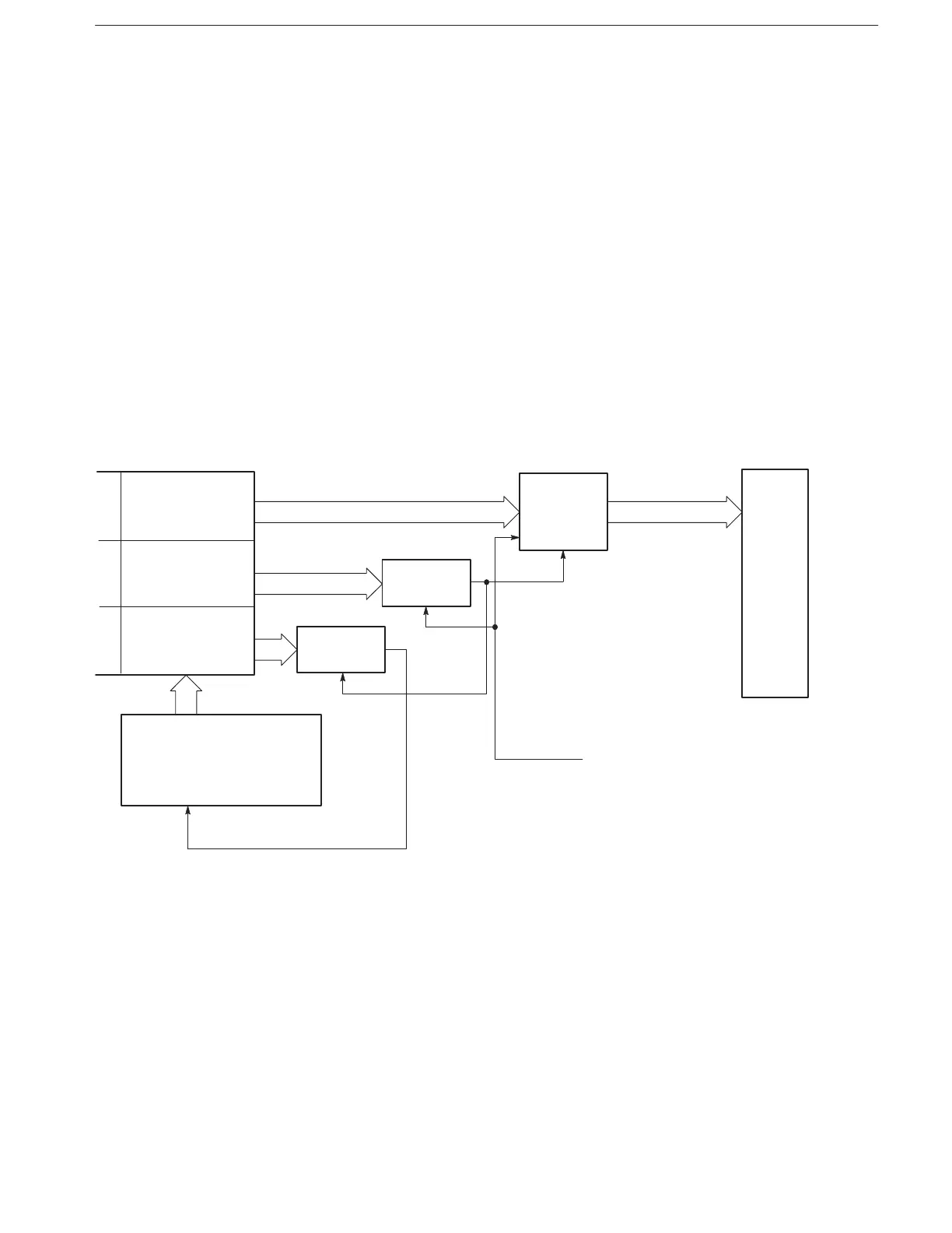
clock). Figure 2–7
shows the relationship between sequence memory and waveform memory.
When running the sample sequence file XXX.SEQ (Table 2–2), the sequence
control system loads the AAA.WFM addresses into the address counter, the
AAA.WFM data length into the length counter, and the looping counter value
into the looping counter. When the system reaches the value set in the looping
counter (3), it increments the sequence memory address counter and reads the
contents of the next step (waveform file
BBB.WFM).
When the user sets a burst count, the system places that value in the burst
counter and outputs the signal the required number of times.
The waveform generator writes the marker signals into waveform memory in the
same manner as waveform data.
Waveform
Memory
Clock (1/8)
Length
Counter
Address
Counter
Looping
Counter
Sequence Memory
Address Counter
Sequence Memory
WFM Address
WFM Data
Length
Looping Control
Value
Figure 2-7: Relationship Between Sequence Memory and Waveform Memory