Functional Overview
2-12
VX4792 User Manual
Earlier in this section we explained you can only set multiples of eight as the
data length, but when data length is small this becomes a problem
If you use triggered mode, you can solve the problem by simply adding data at
the end until the total length is a multiple of eight.
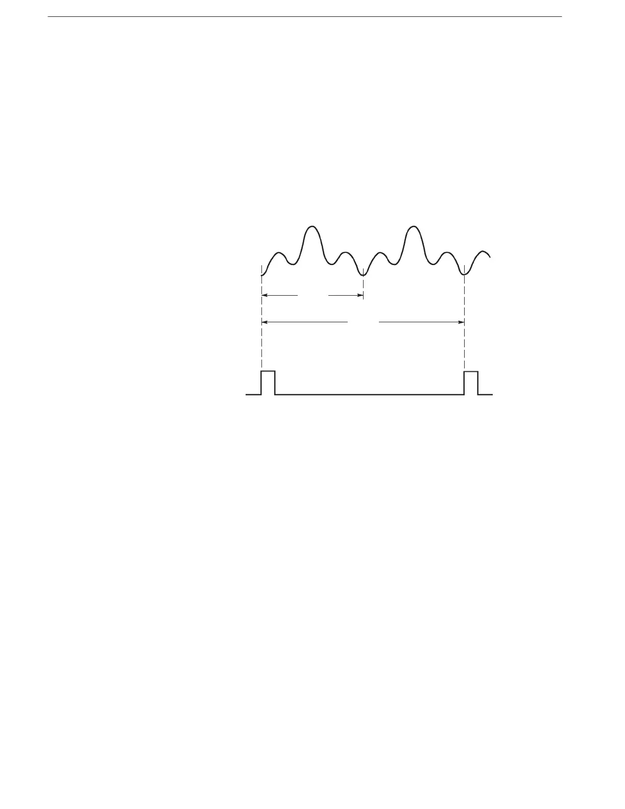
In continuous mode, you should multiply the original data length to achieve a
multiple of eight. For example, if the original waveform has 60 points, connect
two waveforms together to make a waveform with 120 points. Note that when
two waveforms are combined, the waveform generator will generate only one
sync output for each pair of waveforms (see Figure 2–10).
Figure 2-10: Waveform Points and Sync Output in Continuous Mode
Setting Clock Source and Frequency
The clock frequency selected at power-on is 100 MHz using the internal clock
source. You can change the clock frequency and source using the
(page 3–25) and (page 3–26) commands, respectively.
The internal clock frequency range is 10 Hz to 250 MHz. External clock signals
up to 250 MHz may be applied to the CLOCK INPUT connector.
The clock period is the time between the data points for the output waveform.
Therefore, the product of that clock period and the number of waveform points is
the period for that waveform or sequence waveform. For example, suppose the
clock frequency is 1 MHz (for a period of 1 ms). If the waveform has 100 points,
the period for the entire waveform is 100 ms (see Figure 2–11).
When Waveform Data
Length is Not a Multiple
ofĂEight