Performance Verification
VX4792 User Manual
F-31
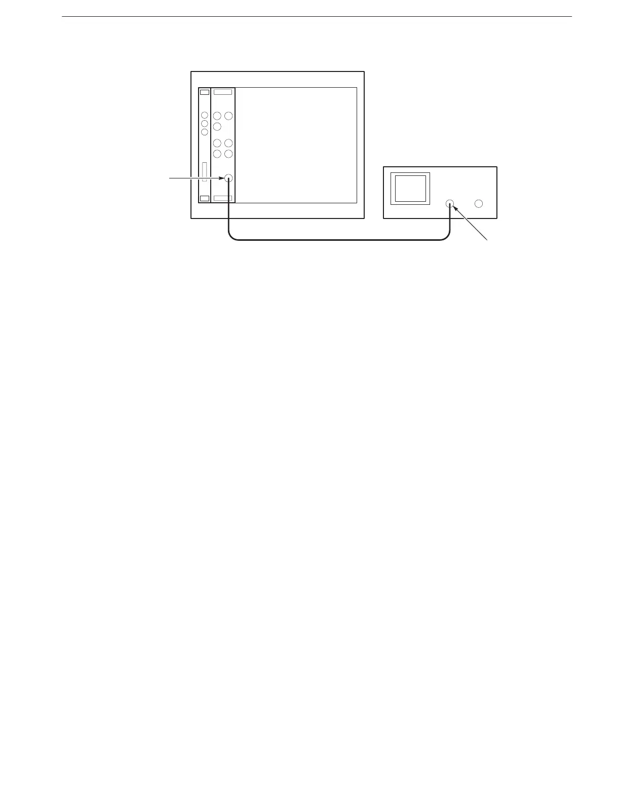
Figure F-15: Pulse Response Initial Test Setup
b. Set oscilloscope controls:
Vertical CH1
Coupling DC
Scale 0.1 V/div
Input impedance 50
Horizontal
Sweep 2 ns/div
Trigger
Source CH1
Coupling DC
Slope Positive
Level 0 V
Mode Auto
2. To set the VX4792 Arbitrary Waveform Generator controls and select the
waveform file, type:
3. Check pulse response at 0.5 V amplitude:
a. Check rise time: Check that the rise time of the waveform displayed on
the oscilloscope from the 10% point to the 90% point is 4 ns or less.
b. Check aberrations: Check that the aberrations of the displayed wave-
form are within 0.45 div.