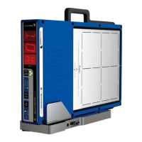
QA BEAMCHECKER™ PLUS 26
• Label: If Static Delivery selected, S01 - S25, if Dynamic Delivery Selected, D01 - D25. Up to 25
different plans for each Static and Dynamic can be used per TomoTherapy System room. Use
this designation to identify which plan is being baselined.
• Dose: Configured dose value of the beam
• Dose Rate: Configured dose rate of the beam. Default is NA (not applicable)
• SAD (Source to Axis Distance) in cm: Default is 85
• Gantry Angle in degrees: Default is 0
• Field Size (x,y) in cm: Default is 5
• Measured by: Name or initials of the baseline creator
• Action Levels: represent the point at which a flatness, axial symmetry, transverse symmetry,
or constancy ‘out of tolerance’ will occur during measurement in Real-Time Operation or Wire-
Free Modes.
If a measured energy differs by or more than the percentage entered in ‘Action Level 1’ box, a
level 1 ‘out of tolerance’ will occur. Likewise, if a measured energy differs at or above the
percentage entered in ‘Action Level 2’ box, a level 2 ‘out of tolerance’ will occur, with Action
Level 2 occurring at a greater percent difference. Default settings are Action Level 1 at 2% and
Action Level 2 at 4%.
• Description: Use this field to help describe the plan. For example, “Jaw Width 2.5 cm Plan C”.
8. Click Proceed to Measurement.
9. Review the entered parameters and ensure the QA BeamChecker Plus is properly aligned
on the treatment couch. By clicking Modify, baseline parameters can be changed on the
previous screen.
NOTE: Verify the QA BeamChecker Plus is flipped to the proper side. The side facing up should
be labeled as Photon or Electron as desired. At this point the software is in control of the mode
settings of the device so if the QA BeamChecker Plus display text orientation is incorrect, verify
the proper room and delivery type in the baseline parameters.
10. The Connection Status should now read as “Ready for Beam” (green), indicating the QA
BeamChecker Plus is ready for exposure. If satisfied with the selected parameters, irradiate the
QA BeamChecker Plus.
11. Upon detecting signal, the QA BeamChecker Plus will begin measurement, and the
Connection Status bar will alternate between green and yellow. Once exposure is completed,
raw measured values will appear on the graphical representation of the QA BeamChecker

 Loading...