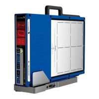
QA BEAMCHECKER™ PLUS 57
The laser test can be incorporated into the baseline and routine measurement procedures for
more comprehensive TomoTherapy QA, but the basic steps are listed below.
1. Place the Precision TomoTherapy Leveling Platform onto the treatment couch and place the
QA BeamChecker Plus onto it ensuring the Photon side is facing up as indicated by the large
white field labels on both sides of the device.
2. Level the top of the QA BeamChecker Plus by placing the precision bubble level at the
center of the top surface and adjusting the three leveling screws on the leveling platform as
needed.
3. Adjust the vertical height using the treatment couch until the horizontal side lasers line up
to the fiducial alignment mark on the top end of the QA BeamChecker Plus facing the bore of
the TomoTherapy unit. After the couch height is correct, align the lasers to the crosshair on the
top surface of the unit.
NOTE: If there is an offset between the green and the red lasers, note this offset by using the
ruled marking on the top surface of the QA BeamChecker Plus. Red lasers should move to the
same position relative to the setup position on a daily basis. Verify leveling is maintained.
4. Now complete an MVCT of the QA BeamChecker Plus by following the directions for
running a procedure on the “What’s Next?” box at the top of the screen in the TomoTherapy
software. After completing the scan, go to the registration panel on the Operator’s Station and
register the MV image to the reference image (taken during the planning step - See Appendix
B) using the manual adjustments. Note registration adjustments.
NOTE: Both the dynamic and static plan can be used to test the accuracy of the movable red
lasers. Use the appropriate plan as described in the Getting Started - TomoTherapy section of
this manual.
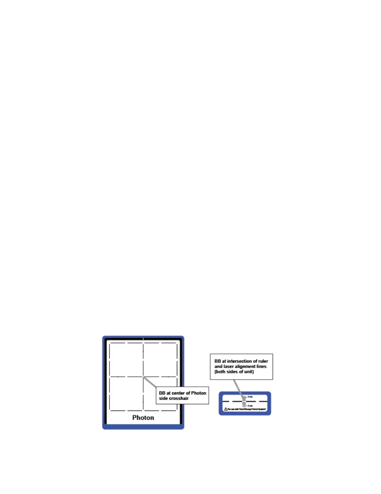
NOTE: There are 1.5 mm BBs located at the center of the crosshairs on the top "Photon"
surface and side labels on the QA BeamChecker Plus. For the longitudinal adjustment, the Y
axis positioning is correct if the BBs show up brightest on the center slice of the MVCT. If they
do not, adjust longitudinal position accordingly until this is the case.