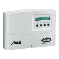
7 Overview of the controller
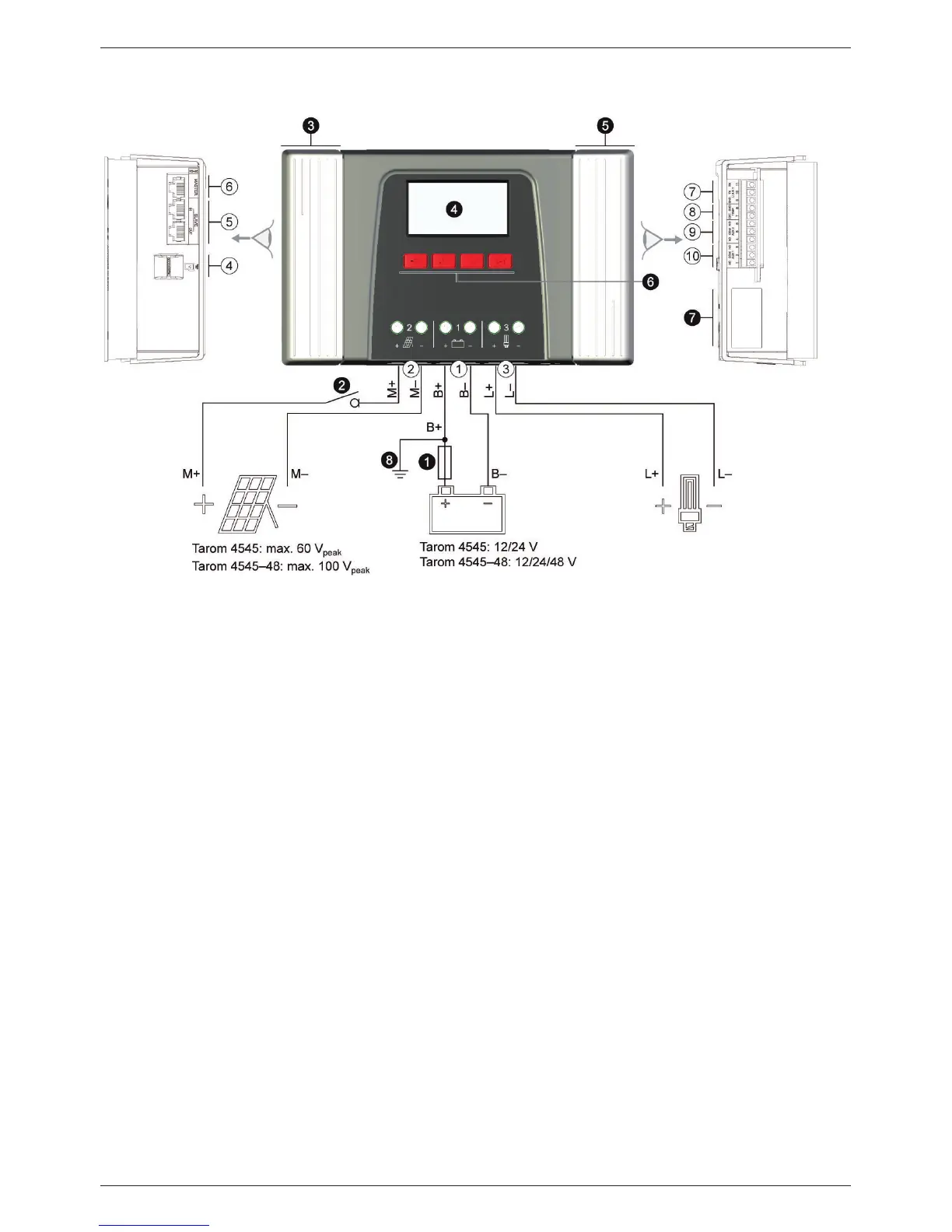
Fig. 1 Overview of casing and connections
1)
Technical data at section 18.1.
2)
Optional
3)
Not included in scope of delivery
Connections
Batteryconnection:terminals1+and1−
Solar module connection: terminals 2+ and
2−
Load output for connecting the loads:
terminals3+and3−
Micro SD slot for microSD card
SLAVE IN and SLAVE OUT RJ45 sockets
for StecaLink Bus
MASTER RJ45 socket for StecaLink Bus
Open UART interface, 3.3 V
Temperature sensor connection TEMP for
Steca PA TS-S
AUX 2 relay output
AUX 1 relay output
Other components
External battery fuse (safety fuse or DC line
circuit breaker
1) 3)
DC load circuit breake
1) 2) 3)
Left cover
Display
Right cover
ESC,
r, s, SET operating buttons
Type plate
Positive ground, optional