4. On the last slave member, terminate the free 'StecaLink Slave' connection with the terminati-
on plug.
5. Register and configure the added StecaLink slave devices on the master device, see section
14.3.9.2 ' StecaLink master setting'.
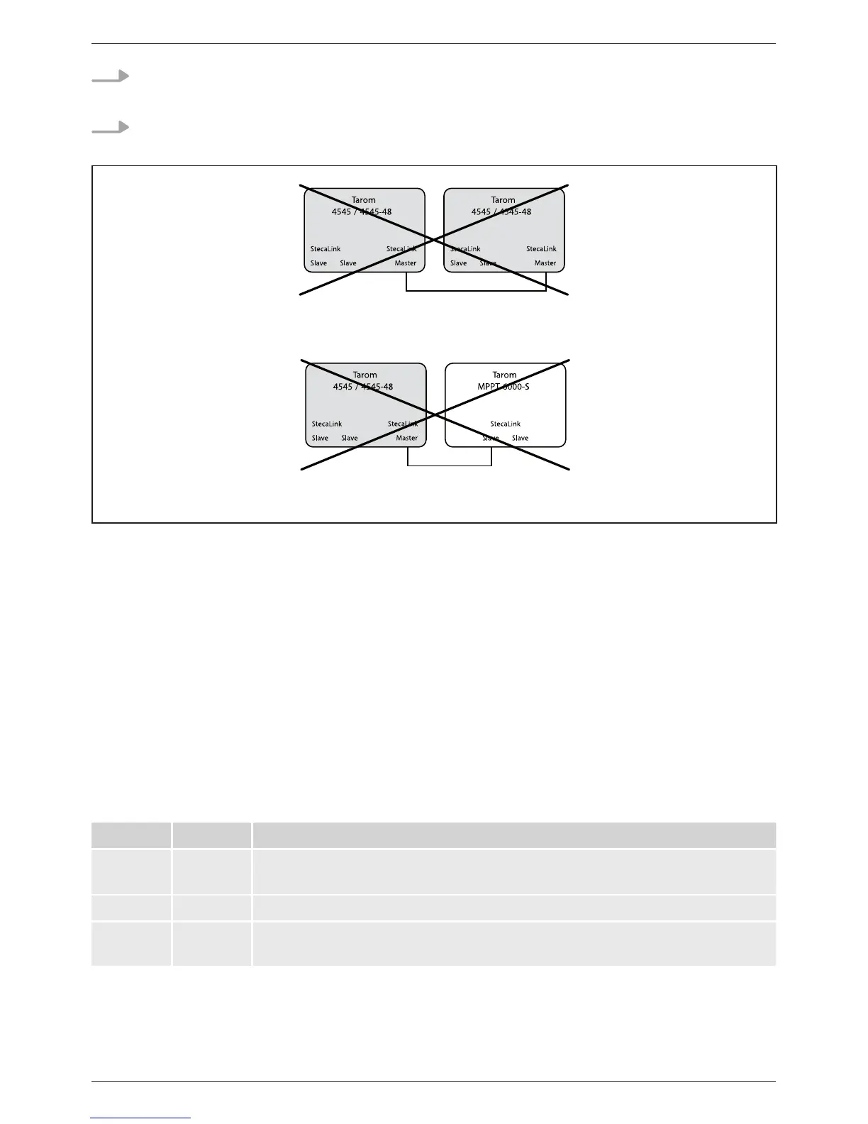
Fig. 7 Master/slave connection of two Tarom 4545/4545-48 via the master connection
is not possible
Fig. 8 Tarom 4545/4545-48 / Tarom MPPT 6000-S connection is not possible without Tarom
MPPT 6000-M
StecaLink bus cable pin assignment: see page 23.
9.2.3 Slot for microSD card ( in Fig. 1)
Data can be logged and parameters can be saved on an inserted microSD card (not included in
scope of delivery). See 'Commissioning of the microSD card' in section 9.5.5.
9.2.4 Relay outputs AUX 1, AUX 2 (, in Fig. 1)
The relay outputs can be used for switching devices or loads (loads via an external power relay).
Devices connected to the relay outputs are controlled via the control functions provided by the con-
troller. Relay output pin assignments:
AUX 1 AUX 2 Description
1 (NC) 4 (NC) Normally closed relay contact; the contact is closed when the relay is
switched off.
2 (COM) 5 (COM) Common relay contact
3 (NO) 6 (NO) Normally open relay contact; the contact is open when the relay is
switched off.