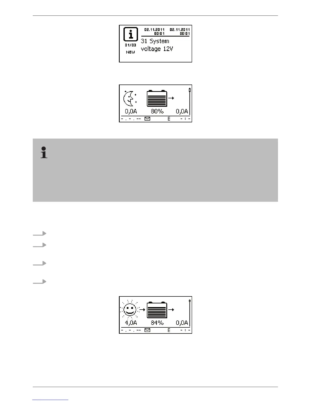
Fig. 11 Event message with the detected system voltage (in the example: 12 V)
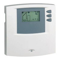
Fig. 12 Basic setting of the status display
9.5.3 Connecting the solar module
1. Safely cover the module (wind)
2. Connect the module cable and optional DC load circuit breaker to the solar module connec-
tion of the controller and to the solar module.
3. Remove covers from the solar module and, if present, switch on the DC load circuit breaker.
The display shows Fig. 13 or Fig. 14.
4. If Fig. 13/Fig. 14 is not displayed, check the installation and if necessary correct the error on
the basis of section 15.
Fig. 13 Display with sunshine after connecting the solar module (possibly delayed)
The battery can be charged from multiple sources. The following applies:
– The battery can be charged by multiple controllers connected to the battery in parallel.
– Apart from the controller, other suitable charging sources can also be connected to the bat-
tery. These charging sources can be switched on and off by the controller via the
‘AUX 1’ and ‘AUX 2’ relay outputs.