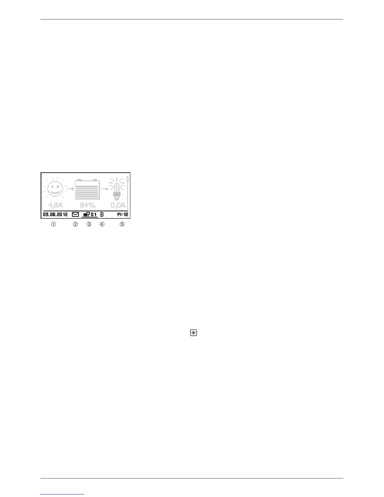
Q Total discharge current of the battery: total of all battery
discharge currents of the components that have been activated
in the menu ’Battery settings’
’Battery control mode’ ’Sen-
sor member list’. Display of the current median in A.
Q Total charge current of the battery: total of all battery charge
currents of the components that have been activated in the
menu ’Battery settings’
’Battery control mode’ ’Sensor
member list’. Display of the current median in A.
Attention
The controller is not approved as a calibrated measuring
device.
Information bar
Date
Symbol for unacknowledged event messages; more informa-
tion on this is provided in section 15.1.
Connect symbol with 2-digit StecaLink slave address; indicates
data traffic on the StecaLink bus.
Symbol for the charging function being executed at the
moment:
‘E’ (equalise charge)
‘F’ (float charge)
‘B’ (boost charge)
‘S‘ (StecaLink slave mode active)
Time
13.3 Display of special states
Q When the inverter is processing large amounts of data it is not able to process any user input.
This is indicated by an animated sun symbol:
Q The backlight flashes red when faults occur. An event message is also displayed.
Q The display can also temporarily malfunction when the controller is operated outside the per-
missible temperature range.