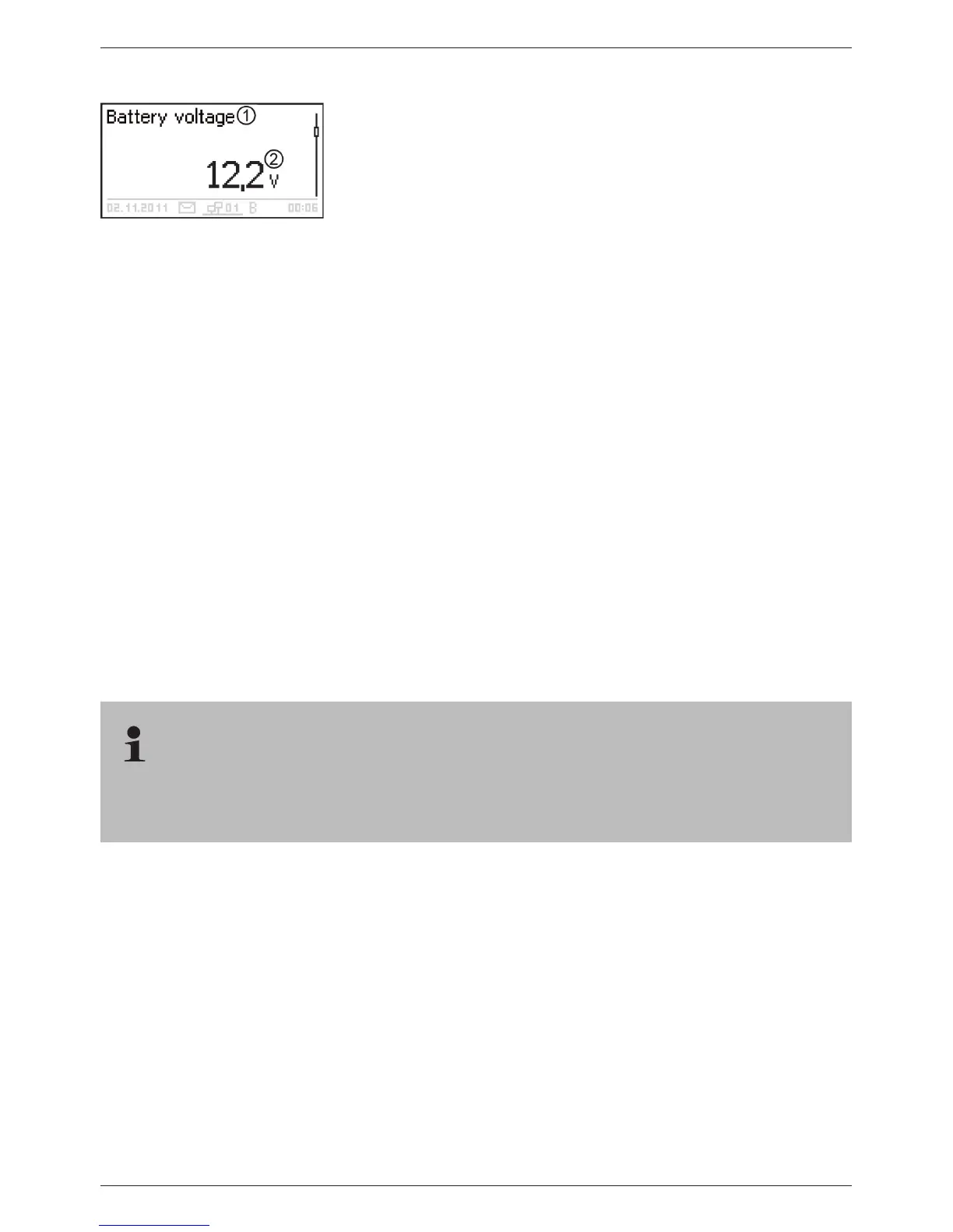
Measured values
Name of the measured value
Measurement with units
The following measurements are displayed:
Q Battery voltage
Q SOC: battery state of charge in % (only shown in SOC control)
Q PV current: presently available max. module current
Q Input current: amount of PV current that is actually being
used.
Q Charge/discharge current:
Positive = current flowing from controller to battery
Negative = current flowing from battery to controller
Q Load current: current from the controller to the loads
Q Daily input
1)
: the daily energy supplied by the modules
Q Daily load
1)
: the daily energy supplied to loads (connected to
the controller)
Q Device temperature
Q Battery temperature
Q Remaining battery capacity (usable)
Note
As the battery capacity changes over time, the displayed remai-
ning capacity may deviate from the actual remaining capacity.
Q Operating hours
Q
Q
Total charge/discharge current of the battery: total of all curr-
ents of the components that have been activated in the menu
’Battery settings’
’Battery control mode’ ’Sensor member
list’. Display of the current median in A.
1)
Generators/loads that are not connected directly to the device must be covered by the device
specific Steca current sensor PA HS400 to allow for correct values to be displayed (depending on the
sensors selected in the data logger).
The following display of information on currents of additional StecaLink slave devices (only on
the master): extent and designation of the representation depends on the respective slave and
its settings.