Chapter 7 Parameter Explanation
Shanghai Sigriner STEP Electric Co., Ltd.
- 108 -
connected, otherwise it is disconnected.
28: Output X1
The level state of the input terminal X1 is output through the output terminal.
29: Output X2
The level state of the input terminal X2 is output through the output terminal.
30: Undervoltage lockout stopping
System undervoltage, and the output terminal outputs an effective level.
31: Fan control
Inverter running or overheating, output terminal connected, otherwise disconnect after a delay of one
minute.
32: Analog input disconnection
33: Motor PTC overheating
34: Reversing status
Note:
1 The meaning of "ON" mentioned above is: for relay output, normally open contacts (1B
and 1C, 2B and 2C) connected, normally closed contacts (1B and 1A, 2B and 2A)
disconnected; for open collector output, it means that the output point is in a low level
status. Similarly, in terms of the above-mentioned "disconnected": for relay output, it
means that the normally opened contacts (1B and 1C, 2B and 2C) are disconnected and
normally closed contacts (1B and 1A, 2B and 2A) are connected; for open collector output,
it means that the output point is in a high impedance state.
2 Factory setting, p 31.04 = 3, Y0 port is designated as the running signal (RUN) output port;
P31.05 = 2, Y 1 port is designated as the output port of the inverter fault signal.
3 Running signal (RUN): The inverter will give the running signal (RUN) only when it
receives the up/down direction command signal and there is no base electrode locking.
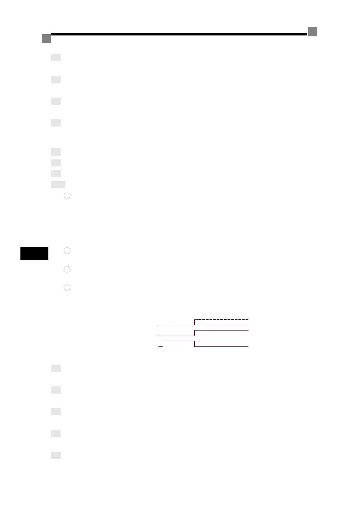
4 Timing of fault signal: In case of any inverter fault, the fault signal will be output. At the
same time, the running signal will be cleared. The fault signal is latched, which can be
cleared by externally input reset signal, by an operator's reset operation, by power failure,
or after an internally set delay time. The timing of fault signal is shown in Figure 7-15.
Figure 7-15 Timing of Fault Signals
35: Sleeping
Process PID control is in sleeping status
36: Alarm output
Inverter is in the alarm status
37: Amplitude locking and phase locking completed
In the power and variable frequency startup mode, it can realize status switching.
38: Frequency detection 3
The running frequency is between P31.26~P31.27
39: Frequency detection 4
 Loading...