Chapter 7 Parameter Explanation
ET/EP/EH Series Intelligent Flexible Driver Manual
- 91 -
时间
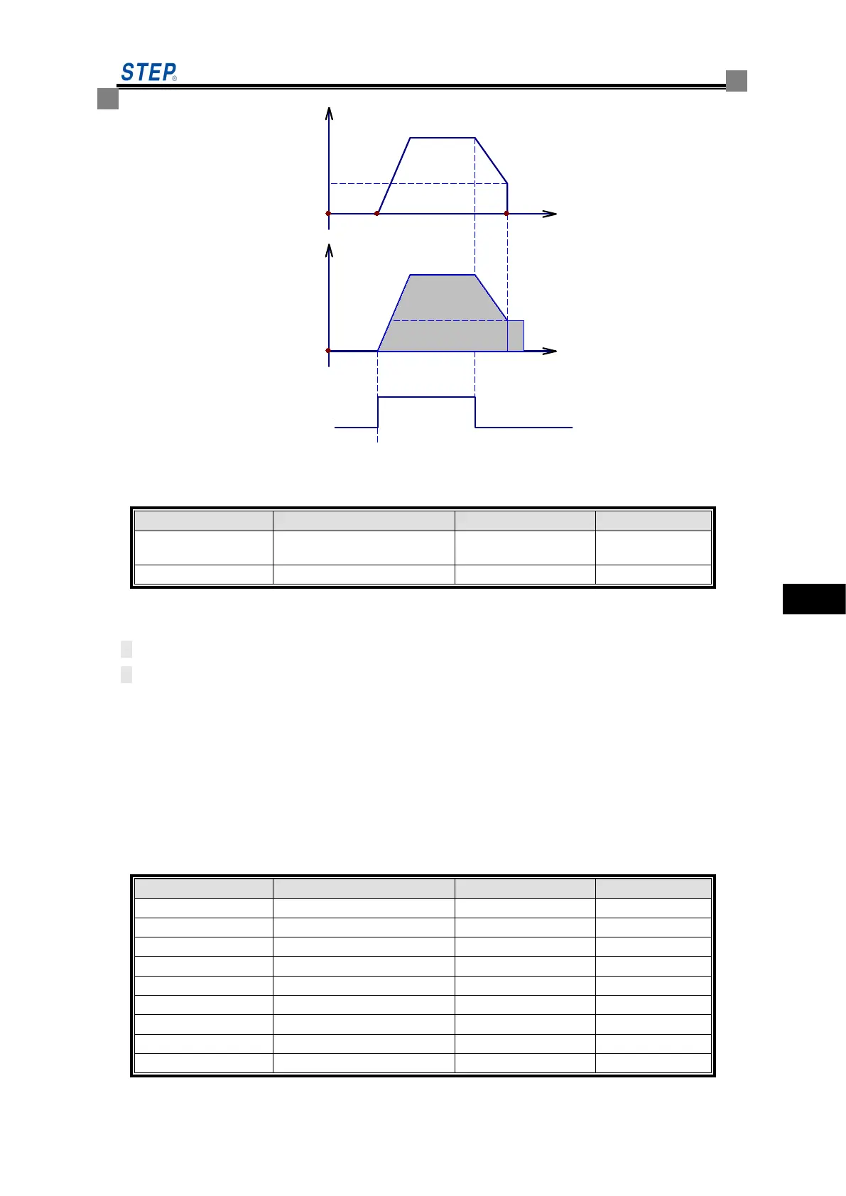
输出频率
0
时间
输出电压
0
运行命令
P12.03
P12.05
P12.04
Figure 7-12 Schematic Diagram of Stopping DC Braking
7.3.4 P13 group Braking function
Energy consumption braking
option
P13.00 energy consumption braking option reflects whether the inverter is designed with energy
consumption braking or not.
1: Energy consumption braking function is enabled.
0: Energy consumption braking function is not used.
For large rotational inertia, if a quick braking stop is required, the matching braking unit and braking
resistor can be selected and the braking parameters can be set to achieve quick braking stop.
The action voltage of the braking unit can be selected by adjusting P13.01. An appropriate action
voltage can be used to realize fast energy consumption braking stop.
Brake switch voltages are divided into two types: at 660 by default, the turning-on voltage is
calculated by the power grid voltage peak;
At non 660, follow the set value.
7.3.5 Group P14 V/F control parameters