ET/EP/EH Series Intelligent Flexible Driver Manual
- 163 -
be as close to the inverter as possible, preferably less than 15 cm; the other point should be on
the grounding bar. The shielding layer should be connected with metal shell of the motor by
360° loop connection at the motor end when it passes through the motor terminal box. In case
of any difficulty, the shielding layer can be twisted into a braid, and then connected to ground
terminal of the motor after flattening, with the flattening width greater than 1/5 of the braid
length. Length of the motor cable core and the lead wire of soft PE braid should be as short as
possible, preferably less than 5 cm.
(4) The shielded cables must be used for the terminal control cables. The shielding layer needs to
be connected to the grounding bar at the entrance of the cabinet by 360° loop connection with
metal cable clamps, and can be fixed to metal case of the inverter with metal cable clamps. In
case of any difficult, the shielding layer can be twisted into a wide and short braid, and then
connected to PE terminal of the inverter after flattening. Length of the exposed part of cable
core and the lead wire of soft PE braid should be as short as possible, preferably less than 15
cm.
(5) The keyboard cable is not allowed to go through the shielding cabinet.
(6) The aperture in the shielding cabinet should be as small as possible, and not exceeding 15 cm.
A.10 EMC standards met by the intelligent flexible driver
After the intelligent flexible driver is installed with appropriate input/output filters and AC reactors
(see "Optional Accessories" for optional filters and reactor models), and wiring by referring to the
above precautions, the EMC standards that can be met are shown in Schedule A.2.
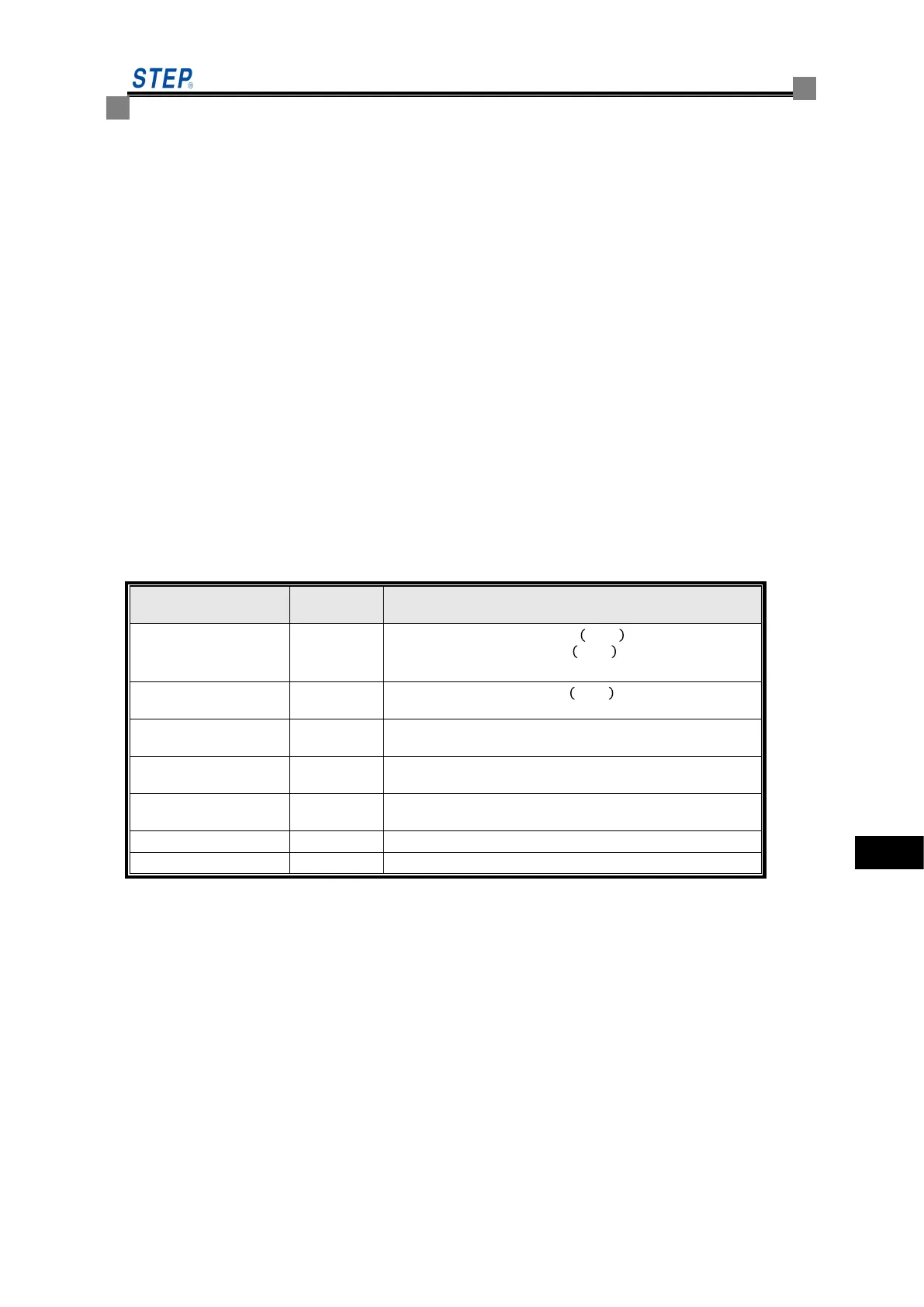
Schedule A.2 Summary of EMC Performance for the Intelligent Flexible Driver
Level of satisfied standard
Conducted disturbance
emission
:
Radiation disturbance
emission
Electrostatic discharge
immunity
Criterion B (contact discharge of 4,000V, air discharge of
8,000V)
Immunity of radiated
electromagnetic field
Level 3 criterion A (3V/m)
Immunity of electrical fast
transient / burst
Level 4 criterion B (± 2KV/2.5kHz at strong electricity terminal)
Criterion A (3V, 0.15~80MHz)