57
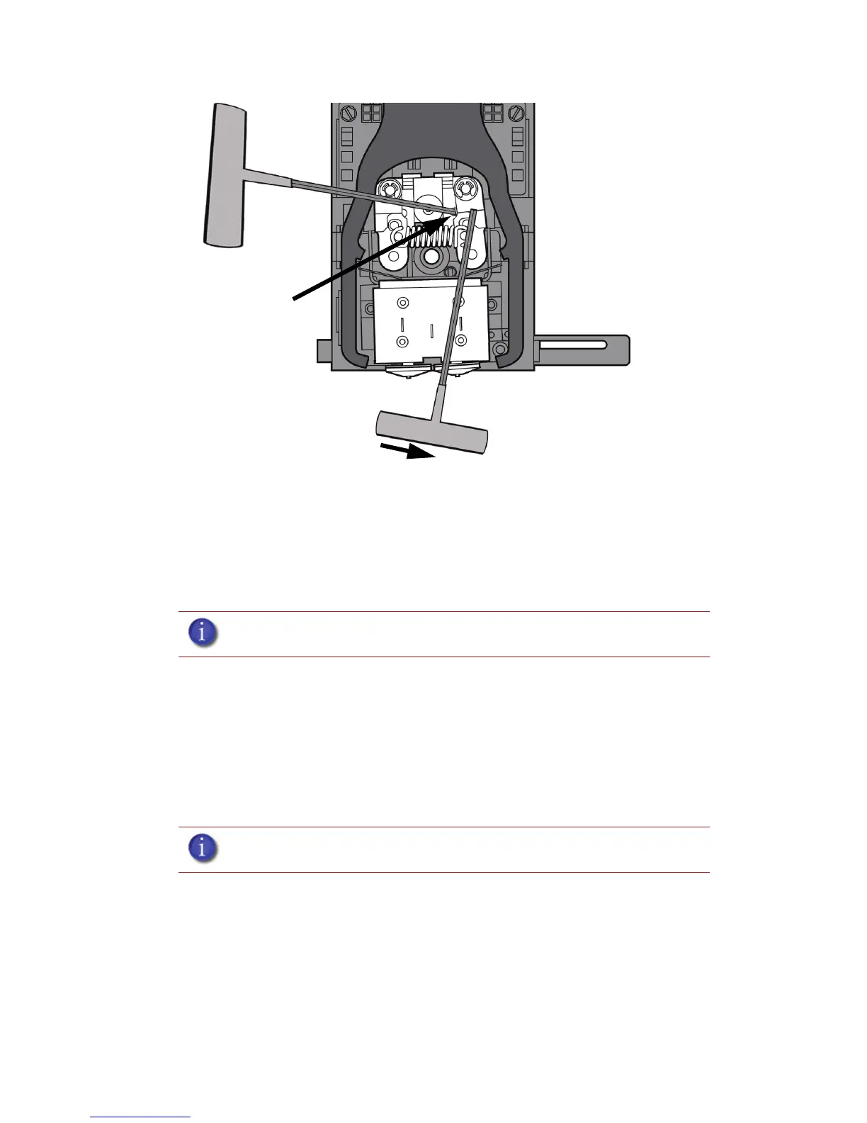
Figure 54 Holding access space open - model side shown
iv. Ease pressure on the 7/64 T-Handle Allen wrench to carefully return the
leveraged idler wheel back toward its original position - until the idler assembly
is resting against the 1/8 T-Handle Allen wrench.
v. Remove the 7/64 T-Handle Allen wrench.
c. Cut the material above the idler wheel using a cutters.
d. Clean the area that is now accessible using a needle nose pliers, a
probe or equivalent tool.
e. Reposition the 7/64 T-Handle Allen wrench between the toggle
spring post and the idler wheel post.
f. Move idler wheel assembly by pushing with 7/64 inch T-Handle
Allen wrench against spring tension and remove the 1/8 T-handled
Allen wrench.
g. Remove the 7/64 T-Handle Allen wrench.
5. Repeat for the opposite side as needed.
6. Replace the head cover.
7. Press Done on the display panel.
8. Display will ask Which Materials Loaded? Press Model if only model material is loaded, press
Support if only support material is loaded or press Both if both model and support material
are still loaded. Press None if neither are loaded.
9. Display will ask you to remove the carrier of the materials that are not loaded. Remove the
carrier and cut the excess material.
10. Press Done until back at Idle.
11. Reload the material that is not loaded.
Note: Make sure that all loose material is removed from the affected area.
Note: If the head cover is not replaced the printer may not function properly.
Insert 1/8 inch T-
Handle into
fixture hole.