• 1/4'' hex wrench
• 3/16'' hex wrench
• 1/2'' combination wrench
• Diagonal pliers
PPrroocceedduurree::
1. Remove the control board assembly. See
Control board assembly removal and replacement
(page 39).
2. Remove the trolley actuator assembly. See
Trolley actuator assembly replacement
(page 40).
3. Unclip the cables from the trolley routing tray and the hydraulic hoses.
4. Unplug the USB quick connect and the D+L-L lock switch cable from the main cable.
5. Position the main cable assembly toward the center of the trolley to allow clearance.
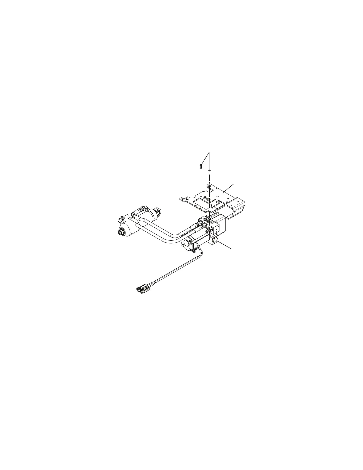
6. Using a T25 Torx driver, remove the two screws (A) that secure the hydraulics assembly (B) to the wing plate, left (C)
(Figure 21).
FFiigguurree 2211 –– HHyyddrraauulliiccss aasssseemmbbllyy
7. Pull outward to remove the pump assembly and set the pump assembly on top of the wing plate, left.
8. Using a 1/4" hex wrench and a 1/2" combination wrench, remove the end cap cylinder pin (D) and nut (E) (Figure 22).
EN 42 6390-309-002 Rev AB.0

 Loading...