C
C
Torque item C
to 235-317 in-lb
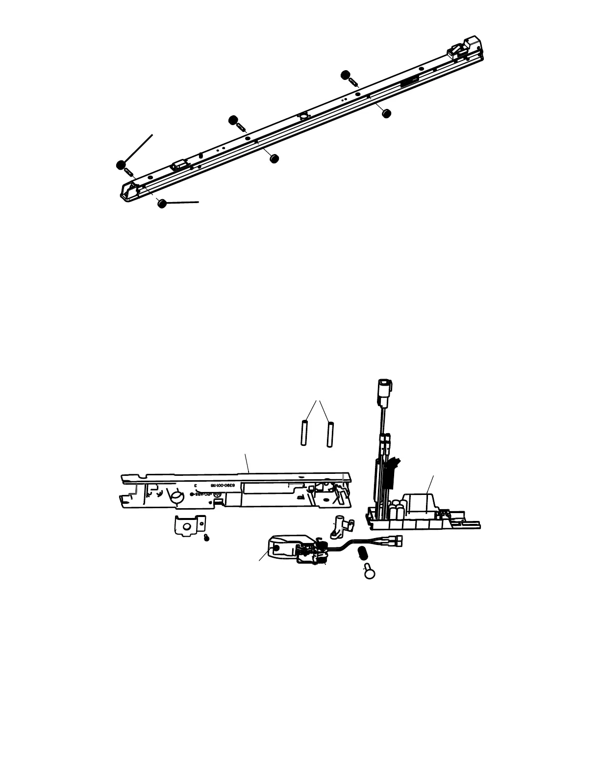
FFiigguurree 4488 –– RReemmoovvee tthhee ffllaatt rroolllleerr aasssseemmbbllyy aanndd VV--gguuiiddee rroolllleerr aasssseemmbbllyy
8. Using a 1/8'' hex wrench, remove two of the four flat head cap screws (D) from one side of the anchor plunger assembly,
mid (Figure 47). Save the screws.
9. Using the second 1/8'' hex wrench, insert the wrench into the anchor pivot pin to remove the other two of the four flat
head cap screws (D) (Figure 47). Save the screws.
10.Unplug the power cables from the extension cable from the underside of the anchor.
11.Remove the anchor plunger assembly, mid (E) from the anchor (Figure 47).
12.Remove the anchor pivot pin (G) that holds the anchor coil assembly (H) to the anchor housing (J) (Figure 49).
13.Unplug the coil wires from the inductive primary board (I) (Figure 49). Discard the anchor coil assembly.
FFiigguurree 4499 –– UUnnpplluugg ccooiill wwiirreess ffrroomm tthhee iinndduuccttiivvee pprriimmaarryy bbooaarrdd
14.Reverse steps to reinstall. Torque the V-guide roller assembly and flat roller assembly to 235-317 in-lb. Torque the
anchor mounting posts to 60±10 ft-lb.
15.Verify proper operation before you return the product to service.
EN 62 6390-309-002 Rev AB.0
 Loading...