Chapter 1 Preparing to Install the Sun Fire X4170, X4270, and X4275 Servers 9
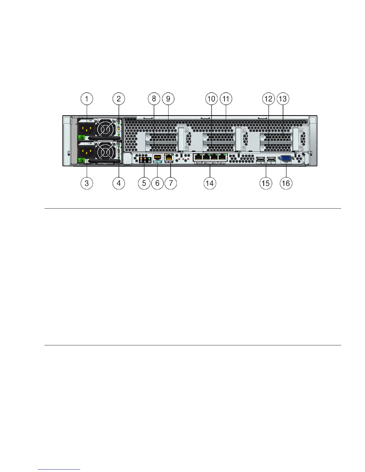
FIGURE 1-6 shows the Sun Fire X4270 and X4275 Servers back panels and describes
their components.
FIGURE 1-6 Sun Fire X4270 and X4275 Servers Back Panel
Figure Leg end
1 Power supply unit 1 connector 9 PCI Express Module slot (3)
2 Power supply unit 1 status indicator LEDs:
Power Supply OK: green
Power Supply Fail: amber
AC OK: green
10 PCI Express Module slot (1)
3 Power supply unit 0 connector 11 PCI Express Module slot (4)
4 Power supply unit 0 status indicator LEDs:
Power Supply OK: green
Power Supply Fail: amber
AC OK: green
12 PCI Express Module slot (2)
5 System status LEDs:
Power: green
Attention: amber
Locate: white
13 PCI Express Module slot (5)
6 Serial management (SER MGT)/RJ-45 serial port 14 Gigabit Ethernet ports NET 0, 1, 2, 3
7 Service processor (SP) network management (NET
MGT) port
15 USB 2.0 ports (0, 1)
8 PCI Express Module slot (0) 16 HD15 video connector (analog VGA)