Chapter 2 Installing Server Options 21
Performing Electrostatic Discharge and
Antistatic Prevention Measures
Electrostatic Discharge Safety Measures
Electrostatic discharge (ESD) sensitive devices, such as the PCIe cards, hard drives,
CPUs, and memory cards, require special handling.
Caution – Circuit boards and hard drives contain electronic components that are
extremely sensitive to static electricity. Ordinary amounts of static electricity from
clothing or the work environment can destroy the components located on these
boards. Do not touch the components along their connector edges.
Caution – You must disconnect both power supplies before servicing some of the
components documented in this chapter.
PCI Slot For Sun Fire X4170 Servers:
1. Remove the server top cover.
2. Remove the PCI slot filler panel from the
location into which you intend to install
the PCIe card.
For Sun Fire X4270 and X4275 Servers:
1. Remote the server top cover.
2. Remove the server crossbar.
3. Remove the PCI slot filler panel from the
location into which you intend to install
the PCIe card.
For Sun Fire X4170 Servers:
1. Remove the server top cover.
2. Press the PCI filler panel into the vacant PCI
slot.
For Sun Fire X4270 and X4275 Servers:
1. Remove the server top cover.
2. Remove the server crossbar.
3. Press the PCI filler panel into the vacant PCI
slot.
4. Replace the server crossbar.
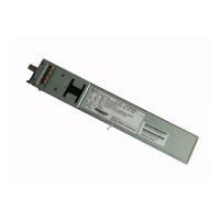
Power supply 1. To release the filler panel side latches,
use your fingers to press and hold both
sides of the filler panel away from the
sides of the power supply bay.
2. Using fingers on your other hand, grasp
the lip at the bottom of the filler panel
and pull it out of the power supply bay.
1. Position the filler panel in the power supply
bay so that the closed end is facing inward
and the lip that is used to remove the filler
panel is in the bottom position.
2. Press the filler panel into the power supply
bay until it is flush with the power supply
bay.
TABLE 2-1 Server Filler Panel Removal and Replacement Procedures (Continued)
Filler Panel Type Removal Procedure Install Procedure