Chapter 4 Setting Up the Server 75
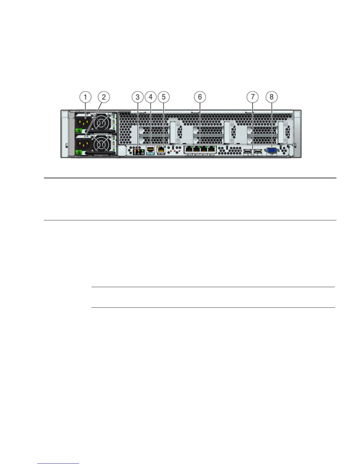
FIGURE 4-2 shows and describes the locations of the Sun Fire X4270 and X4275
Servers back panel connectors
.
FIGURE 4-2 Sun Fire X4270 and X4275 Server Back Panel
▼ Cable the Server
Connect the server power cables and external cables in the following order:
1. Connect two grounded server power cords to grounded electrical outlets.
Note – Connect only one cable if your server does not have a redundant power
supply.
2. Connect the two server power cords to the AC power connectors on the back
panel of the server [1, 2].
In standby power mode, the Power/OK LED on the front panel blinks, indicating
that the service processor (SP) is working as shown in FIGURE 4-3, FIGURE 4-4, and
FIGURE 4-5. At this point, before initial configuration, standby power is supplied only
to the SP and power supply fans.
Figure Leg end
1 Power supply unit 1 connector 5 Service processor (SP) network management (NET
MGT) Ethernet port
2 Power supply unit 0 connector 6 Gigabit Ethernet ports NET-0, 1, 2, 3
3 System status LEDs 7 USB 2.0 ports (0, 1)
4 Serial management (SER MGT)/RJ-45 serial port 8 HD15 video connector (analog VGA)