Chapter 2 Installing Server Options 27
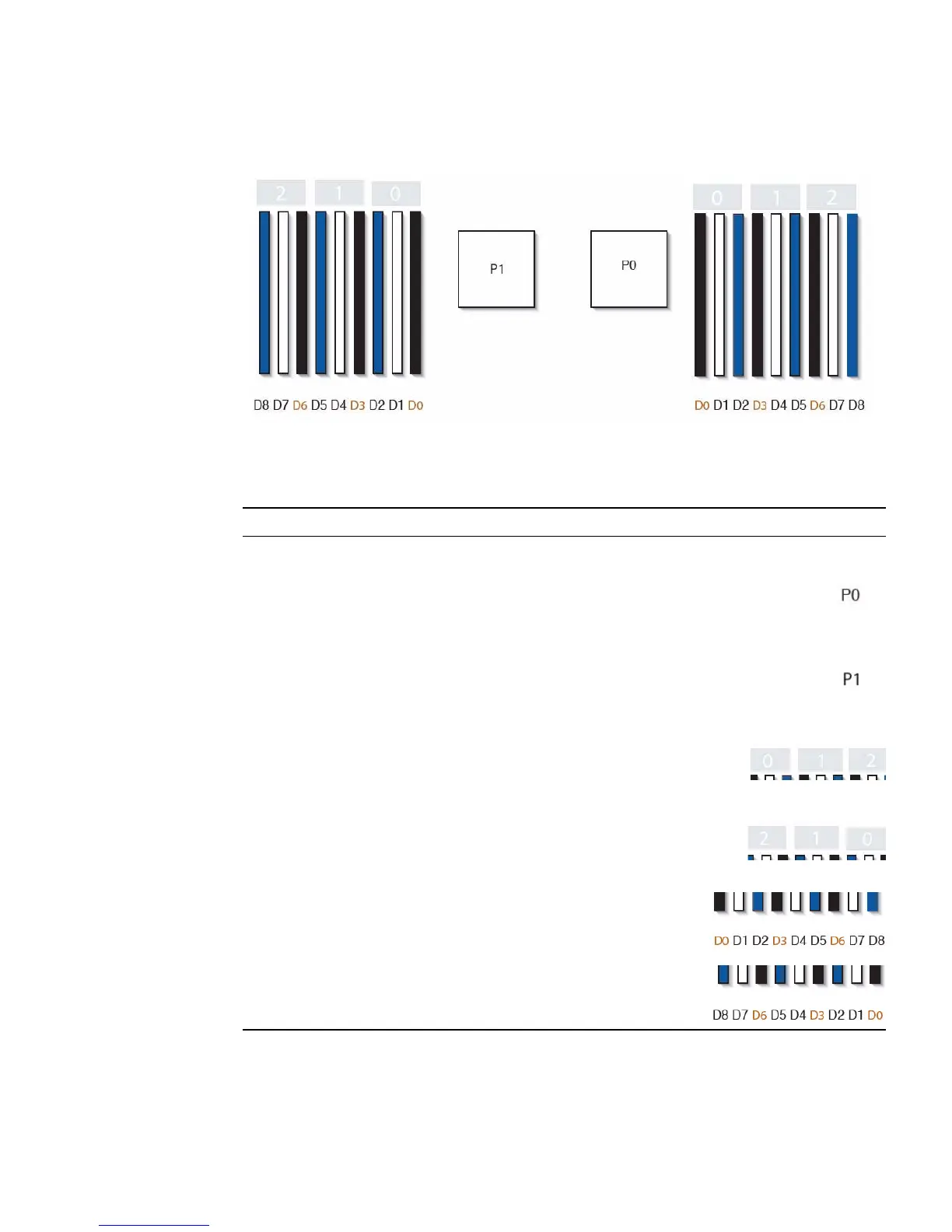
FIGURE 2-3 CPU and DIMM Physical Layout
TABLE 2-2 CPUs and DIMMs Physical Layout
CPUs and DIMMs Physical Layout
CPU 0 location
CPU 1 location
Channel locations for CPU 0
Three channels per CPU with each channel containing three
color-coded DIMM slots (black, white, and blue).
Channel locations for CPU 1
Three channels per CPU with each channel containing three
color-coded DIMM slots (blue, white and black).
DIMM slot numbering per CPU; with D8 as the farthest slot
away from CPU.
P0:
P1: