12
LED Color State Definition
Red
On
A fault occurs and the device cannot connect to the
grid.
Blink
The Bluetooth connection is established, data commu-
nication in process, and a system fault occurs.
Gray
OFF
Both the AC and DC sides are powered down.
Voltage may still be present in AC side circuits after the indicator is off. Pay atten-
tion to the electricity safety when operating.
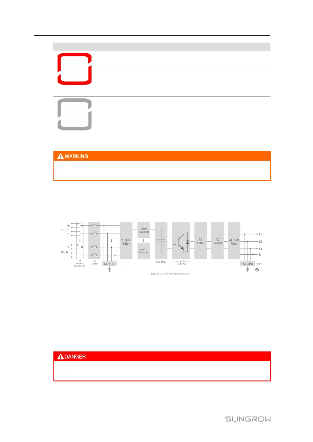
2.5 Circuit Diagram
The following figure shows the main circuit of the inverter.
figure 2-4 Circuit Diagram
• The DC Switch is used to safely disconnect the DC circuit.
• The MPPT is used to ensure a maximum power from PV arrays at different PV input
conditions.
• The Inverter Circuit converts the DC power into AC power and feeds it to loads(if there
are) or utility grid through the AC terminal.
• The protection circuit ensures the safe operation of the device and personal safety.
If the lightning level exceeds the protection level of the product, surge protection
and overvoltage protection may fail, resulting in electric shock and fatal injury!
2 Product Description User Manual
 Loading...