35
The cable colors in figures in this manual are for reference only. Please select ca-
bles according to local cable standards.
5.2 Terminal Description
All electrical terminals are located at the bottom of the inverter.
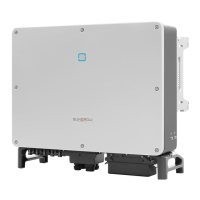
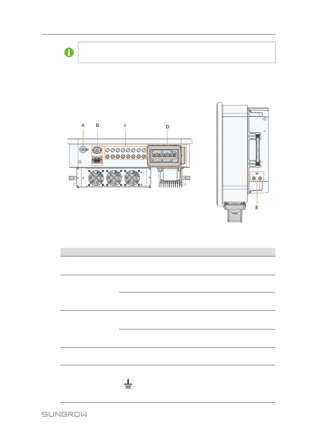
figure 5-1 Terminal Description
* The image shown here is for reference only. The actual product received may differ.
Item Terminal Mark Note
A DC Switch DC SWITCH
Used to switch on and off the DC
input.
B
Communica-
tion terminal
COM1
For communication module
connection.
COM2
DI, DRM, DO, RS485, Smart En-
ergy Meter
C PV terminals
PV1,PV2, PV3, PV4, PV5,
PV6
6 pairs of terminals(SG25/30/
33CX-P2)
PV1,PV2, PV3, PV4, PV5,
PV6, PV7, PV8
8 pairs of terminals(SG36/40/
50CX-P2)
D
AC wiring
terminal
AC
Used for AC output cable
connection.
E
External pro-
tective
grounding
terminal
Used for reliable grounding of
the inverter
2, use at least one of them to
ground the inverter.
User Manual 5 Electrical Connection