36
table 5-1 The label of COM2 terminal
DI DRM DO RS485 Meter
DI DI C D4/8 D2/6 COM B1 B1 B2
PGND PGND R D3/7 D1/5 NO A1 A1 A2
table 5-2 The label description of COM2 terminal
No. Label
Description
1 DI
emergency stop dry contact
2 DRM
• "AU"/"NZ": Demand response enabling device
(DRED)
• "DE": Ripple Control Receiver (RCR)
3 DO
fault output dry contact
4
RS485 (A1, B1)
(1)
• Connect to the Logger, so as to implement data ex-
change with PC or other monitoring devices.
• Enable the communication between inverters in
parallel.
5
Meter (A2, B2)
(1)
Connect to the Smart Energy Meter.
(1) When the inverter is connected to a third-party monitoring device, please confirm which
communication interface is used, and whether it will cause loss of certain functions of the
inverter.
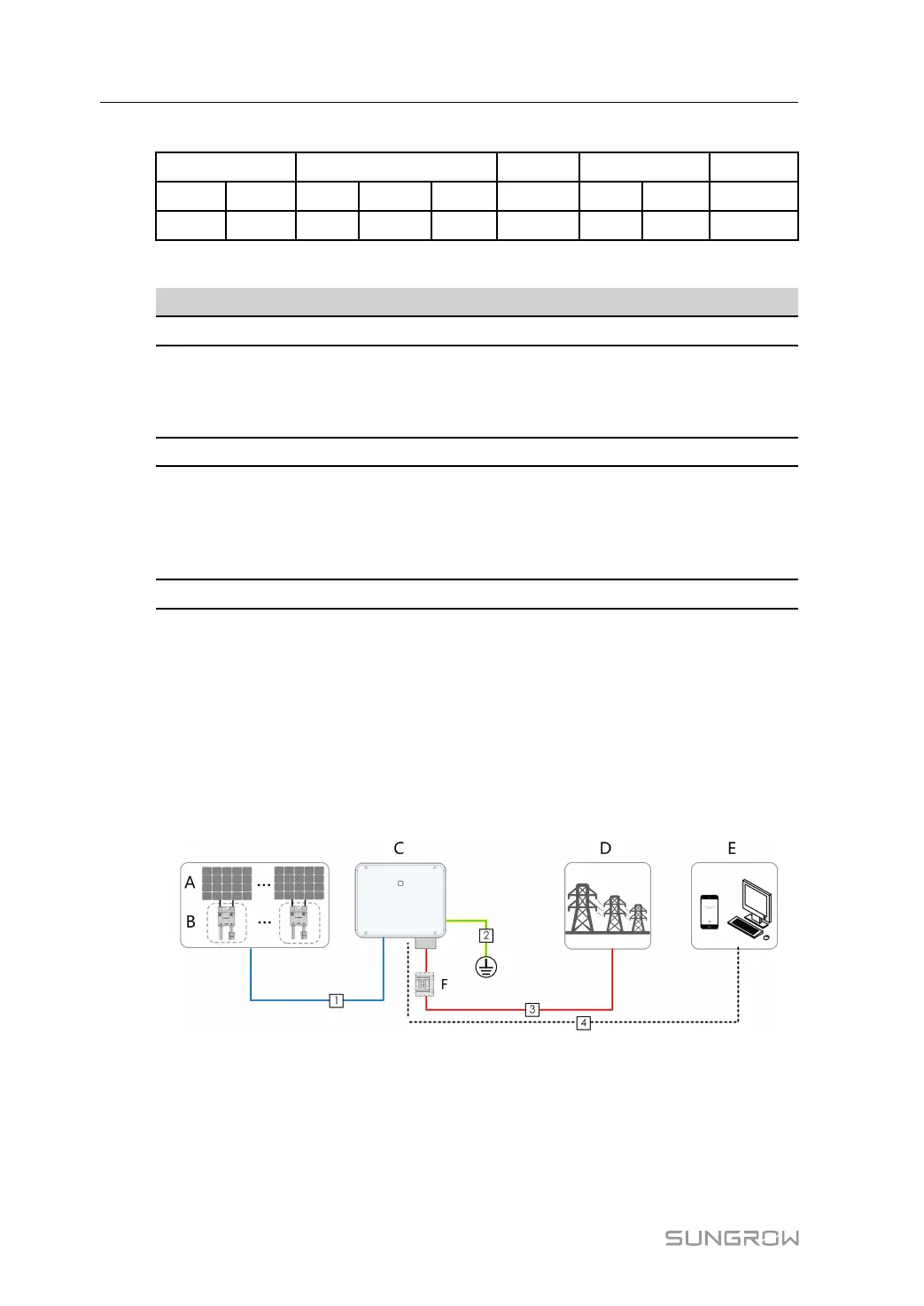
5.3 Electrical Connection Overview
Connecting the inverter to the PV system requires connecting the inverter to the protective
grounding point, to the grid, and to the PV strings.
(A)PV string (B)Optimizer(optional)
(C)Inverter
(D)Grid
(E)Monitoring device
(F)AC circuit breaker
5 Electrical Connection User Manual
 Loading...