64
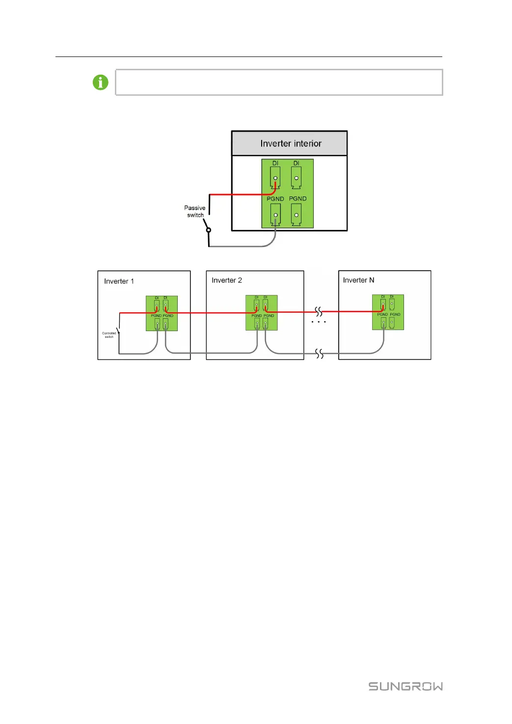
The dry contacts only support passive switch signal input.
The following figure shows the typical application of local stop dry contact.
figure 5-6 Local stop contact
figure 5-7 Daisy chain topology
When wiring DI dry contacts, ensure that the maximum wiring distance meet the
requirements in "10.2 Wring Distance of DI Dry Contact".
5.8.5.2 Wiring Procedure
For detailed connection description of the DI/DO cable, refer to the section "5.8.3 RS485
Connection". Plug the wires into the DI/DO terminal according the labels on the bottom of
the inverter.
5.8.6 DRM Connection
DRM and Ripple Control support only one function at the same time.
DRM
In Australia and New Zealand, the inverter supports the demand response modes as
specified in the standard AS/NZS 4777.
The following figure shows the wiring between the inverter and the external DRED.
5 Electrical Connection User Manual
 Loading...