61
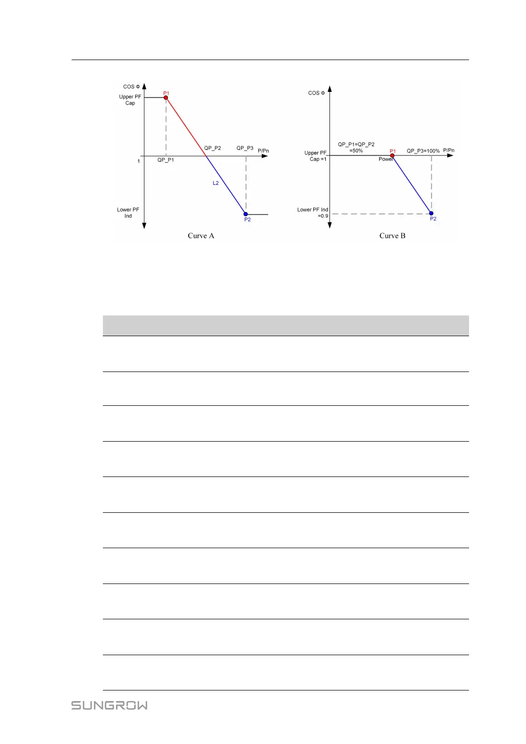
FFiigguurree 77--33 Reactive Power Regulation Curve in Q(P) Mode
""QQ((UU))"" MMooddee
The reactive power output of the inverter varies in response to the grid voltage.
Table 7-3 "Q(U)" Mode Parameter Explanation
PPaarraammeetteerr
EExxppllaannaattiioonn RRaannggee
Q(U) curve
Select corresponding curve according to local
regulations
A, B, C
*
Hysteresis
Ratio
Voltage hysteresis ratio on the Q(U) mode curve
0.0 %–5.0 %
QU_V1
Grid voltage limit at point P1 on the Q(U) mode
curve (in %)
80.0 %–100.0
%
QU_V2
Grid voltage limit at point P2 on the Q(U) mode
curve (in %)
80.0 %–110.0
%
QU_V3
Grid voltage limit at point P3 on the Q(U) mode
curve (in %)
100.0 %–
120.0 %
QU_V4
Grid voltage limit at point P4 on the Q(U) mode
curve (in %)
100.0 %–
120.0 %
QU_Q1
Value of Q/Sn at point P1 on the Q(U) mode curve
(in %)
-60.0 % to 0.0
%
QU_Q2
Value of Q/Sn at point P2 on the Q(U) mode curve
(in %)
-60.0 % to 60.0
%
QU_Q3
Value of Q/Sn at point P3 on the Q(U) mode curve
(in %)
-60.0 % to 60 %
QU_Q4
Value of Q/Sn at point P4 on the Q(U) mode curve
(in %)
0.0 % to 60.0 %
User Manual 7 iSolarCloud App