1D-39 Engine Mechanical:
Cam Chain Tensioner Inspection
BA02J21406024
Inspect the cam chain tensioner in the following
procedures:
1) Remove the cylinder head. Refer to “Engine Top
Side Disassembly” (Page 1D-27).
2) Remove the starter idle gears and magneto rotor.
Refer to “Starter Torque Limiter / Starter Idle Gear /
Starter Clutch Removal and Installation” in Section 1I
(Page 1I-10).
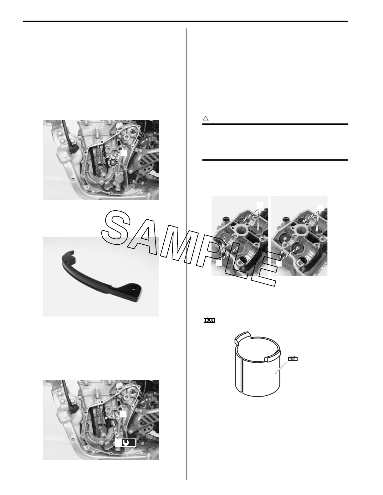
3) Remove the cam chain tensioner (1).
4) Check the contacting surface of the cam chain
tensioner. If it is worn or damaged, replace it with a
new one.
5) Install the cam chain tensioner (1) and tighten the
cam chain tensioner mounting bolt (2) to the
specified torque.
Tightening torque
Cam chain tensioner bolt (a): 10 N·m (1.0 kgf-m,
7.0 lbf-ft)
6) Reinstall the magneto rotor and starter idle gears.
Refer to “Starter Torque Limiter / Starter Idle Gear /
Starter Clutch Removal and Installation” in Section 1I
(Page 1I-10).
7) Reinstall the cylinder head. Refer to “Engine Top
Side Assembly” (Page 1D-30).
Cylinder Head Disassembly and Assembly
BA02J21406025
Refer to “Engine Top Side Disassembly” (Page 1D-27)
and “Engine Top Side Assembly” (Page 1D-30).
CAUTION
!
Identify the position of each removed part.
Organize the parts in their respective groups
(i.e., intake, exhaust) so that they can be
installed in their original locations.
Disassembly
1) Remove the tappets (1) and shims (2) by fingers or
magnetic hand.
2) When compressing the valve spring, use the sleeve
protector. Cut the sleeve protector as shown in the
illustration.
Special tool
(A): 09919–28610 (Sleeve protector)
1
IA02J1140237-01
IA02J1140238-01
11
(a)
2
IA02J1140239-01
1
1
2
2
IA02J1140014-01
(A)
IA02J1140015-01

 Loading...