Drive Chain / Drive Train / Drive Shaft: 3A-9
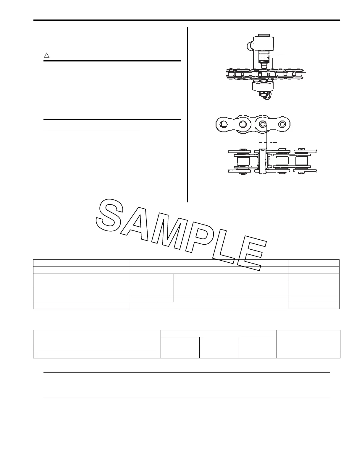
2) Stake the joint pin by turning (approximately 7/8 turn)
the pressure bolt [A] (3) with the bar until the pin end
diameter becomes the specified dimension.
CAUTION
!
• After joining of the chain has been
completed, check to make sure that the
link is smooth and no abnormal condition
is found.
• Should any abnormal condition be found,
reassemble the chain link using the new
joint parts.
Pin end diameter specification “a”
DID: 5.5 – 5.8 mm (0.22 – 0.23 in)
3) Adjust the drive chain slack, after connecting it.
Refer to “Drive Chain Inspection and Adjustment” in
Section 0B (Page 0B-20).
Specifications
Service Data
BA02J23107001
Drive Train
Unit: mm (in) Except ratio
Tightening Torque Specifications
BA02J23107002
NOTE
The specified tightening torque is described in the following.
“Drive Chain Related Components” (Page 3A-2)
“Drive Chain Roller Construction” (Page 3A-3)
Reference:
For the tightening torque of fastener not specified in this section, refer to “Tightening Torque List” in Section 0C
(Page 0C-8).
3
I649G1310035-02
“a”
I649G1310036-03
Item Standard Limit
Final reduction ratio 3.923 (51/13) —
Drive chain
Type DID 520MXV —
Links 114 links —
Drive chain plate height
Inner 15.0 (0.59) 12.75 (0.502)
Outer 12.8 (0.50) 11.20 (0.441)
Drive chain slack 40 – 50 (1.6 – 2.0) —
Fastening part
Tightening torque
Note
N⋅mkgf-mlbf-ft
Engine sprocket cover bolt 11 1.1 8.0 )(Page 3A-4)
Rear sprocket nut 30 3.0 21.5 )(Page 3A-5)

 Loading...