NTRODUCTION
➁
➀
Su
ie
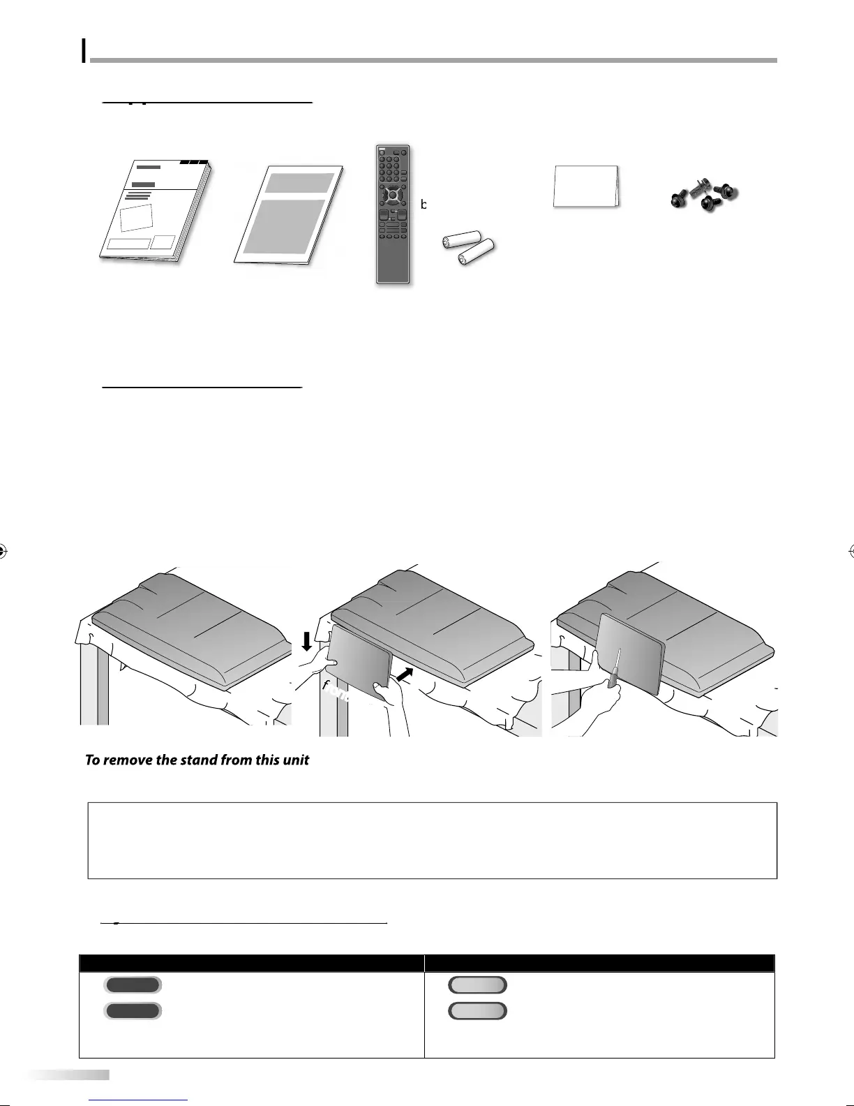
Accessorie
You must attach the stand to the unit to have it as a table to
unit. Be sure the
ront and rear o
the stand match the
ro
er direction
• When attaching the stand, ensure that all screws are tightl
fastened. If the stand is not properl
attached, it could cause the unit to fall,
resu
tin
in in
uries as we
as
ama
e to t
e unit
• Make sure to use a table which can support the weight of this unit and is larger than this unit.
• M
k
r
h
l
i
in
l
l
i
n
I
you need to replace these accessories, please re
er to the part No. with the illustrations and call our toll
ree
ustomer support line
ound on the cover o
this manual
Symbols Used in this Manual
The following is the description for the symbols used in this manual. Description refers to
TV FUNCTIONS DVD FUNCTIONS
Analo
TV operatio
Playback o
DVD-video
: Digita
TV operatio
Playback o
audio CD
• I
neither symbol appears under the
unction heading,
operation is app
ica
e to
ot
• I
neither symbol appears under the
unction heading,
peration is app
ica
e to
ot
.
1
S
read a thick and soft cloth over a
l
h
wn
l
w
Pl
h
m
in
ni
f
wn
n
i
ake sure not to dama
e the screen.
t least 2
eo
le are re
uired at this
ste
.
2
Ali
n the 2 stand hooks with the two
k
n
r
h
m
f
h
m
in
nit (shown b
arrow
then slide
h
n
in
h
ir
i
n
h
wn
arrow
until it sto
s and the
ountin
holes are ali
ned.
ake sure not to
ut the AC
ower
r
w
n
h
n
n
h
ni
3
Drive Philli
s
an screws in
hr
h
l
h
m
f
h
stand until the
are tight.
Unscrew t
e P
i
ips pan screws on step 3
A
ter the screws are removed pull the stand up toward the rear o
the unit. Be care
ul not to drop the stand when you remove it.
wn
r’
m
n
1EMN25921
uic
start
ui
e
1EM
r
m
n
r
NF033UD
ri
.
re
istration car
1EMN24700
r
w ki
r
ttac
ing t
e stan
1ESA19508
A9DF1UHLD320SS1ENv1.indd4A9DF1UHLD320SS1ENv1.indd4 2010/01/2219:09:332010/01/2219:09:33
 Loading...