102 Preparation for Operation TB7100 Installation and Operation Manual
© Tait Electronics Limited December 2005
7.6.1 Link Settings
Remove the cover as detailed in “Removing the Base Station and Opening
the Tray” on page 54 and set the following links on the SI board.
Links of the mandatory settings must be in the position indicated. Links of
the optional settings must be in one of the positions listed. The defaults are
generally recommended.
Replace the cover as detailed in “Final Reassembly” on page 63.
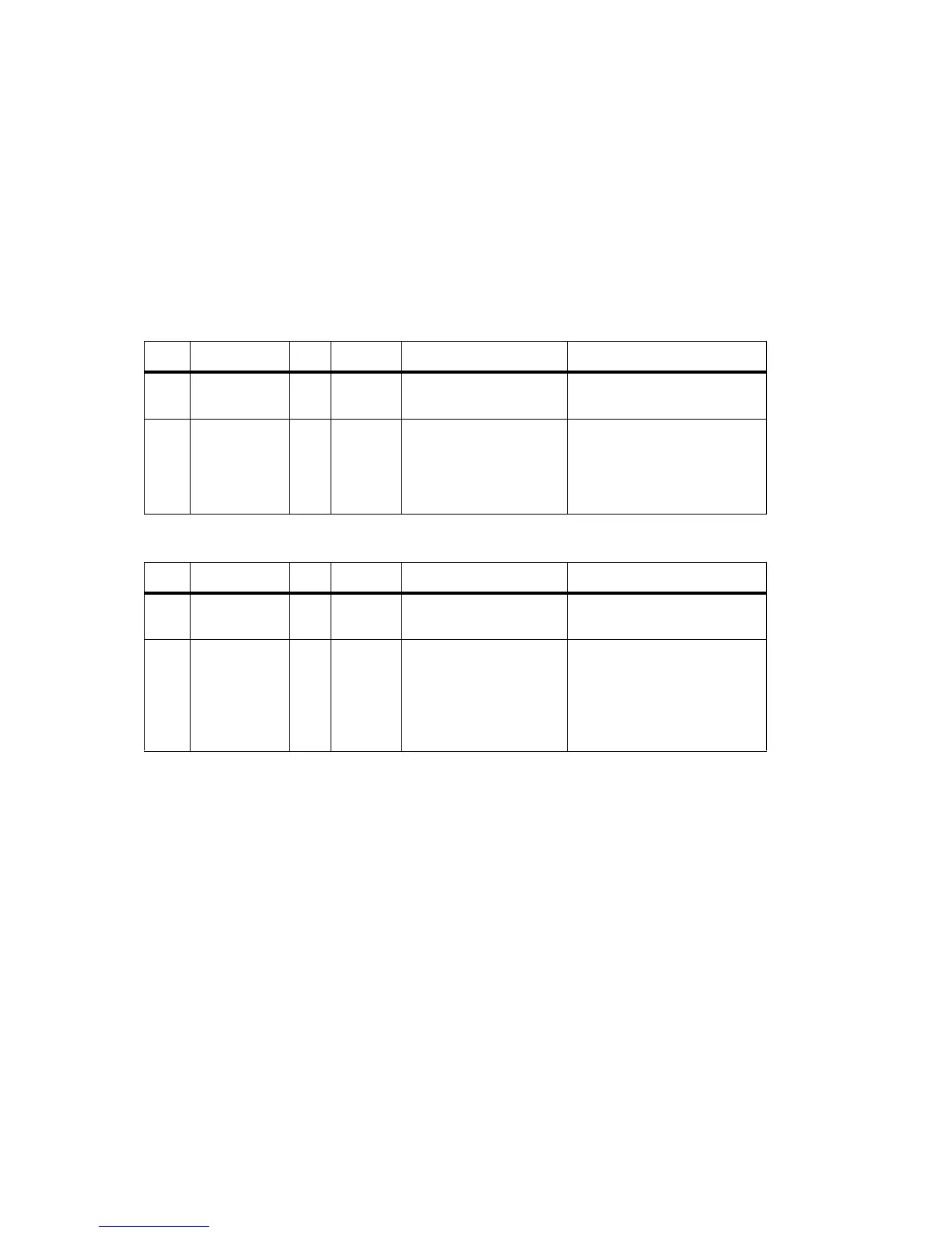
Table 7.7 Data repeater—mandatory settings
LINK Name Pins Position Function Comments
J221 RS232 Loop
Back
3 2-3 RS-232 looped back
J400 Tx Key
Source
3 1-2 External Tx key source Use this setting because the
transmitter will automatically key
up when there is data to send so
should not be keyed by the
receiver gate.
Table 7.8 Data repeater—optional settings
LINK Name Pins Position Function Comments
J206 Fan Control 1 3 1-2
2-3
Fan controlled by J207
Fan always on
Default position is 1-2
J207 Fan Control 2 3 2-3 Fan temperature-controlled Do not use position 1-2 (Tx key-
activated fan). The transmitter will
automatically key up when there
is data to send. This will not
activate the Tx key line and
therefore will not activate the fan.

 Loading...


