TB7100 Installation and Operation Manual Preparation for Operation 95
© Tait Electronics Limited December 2005
7.5.4 Applying Power
Before turning on the base station, check that:
■ all looms and cables at the front and rear of the base station are fitted
correctly
■ all connectors are secure
■ the 20A fuse is fitted.
Turn on the power supply and check that the base station powers up
correctly:
■ The power LED on the user interface lights up.
■ The LCD indicates the current channel number.
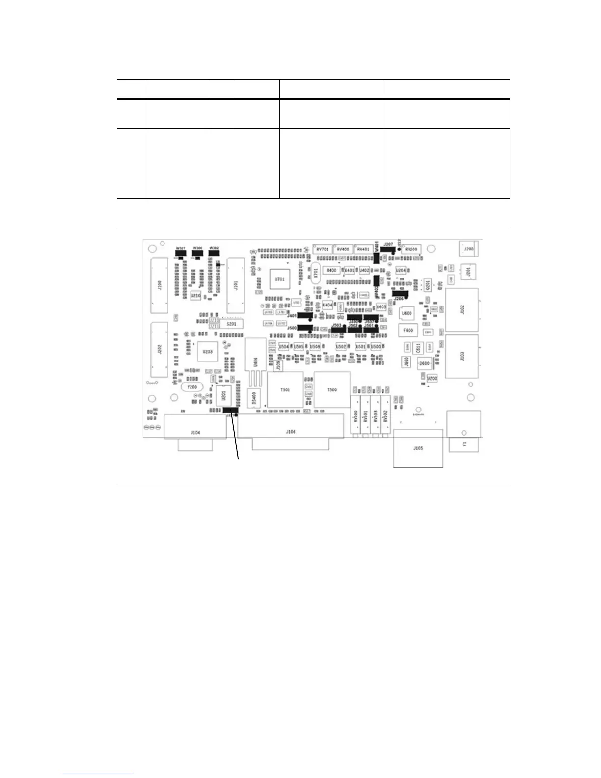
Table 7.6 RF modem—optional settings
LINK Name Pins Position Function Comments
J206 Fan Control 1 3 1-2
2-3
Fan controlled by J207
Fan always on
Default position is 1-2
J207 Fan Control 2 3 2-3 Fan temperature-controlled Do not use position 1-2 (Tx key-
activated fan). The transmitter will
automatically key up when there
is data to send. This will not
activate the Tx key line and
therefore will not activate the fan.
Figure 7.6 System interface link positions
J221

 Loading...


