TB7100 Installation and Operation Manual Preparation for Operation 89
© Tait Electronics Limited December 2005
7.4.2 Test Equipment Setup
1. Connect the PC to the programming port on the front panel of the
base station. See “Connecting to the PC” on page 105.
2. Connect the receiver N-type connector to the RF test set (signal
generator) output port.
3. Connect the transmitter N-type connector to the RF test set (power
and modulation meter) input port, check the test set is rated for the
transmit power of the base station.
4. Connect the 13.8V power supply to the DC input on the base station,
ensuring correct polarity.
7.4.3 Link Settings
Remove the cover as detailed in “Removing the Base Station and Opening
the Tray” on page 54 and set the following links on the SI board.
Links of the mandatory settings must be in the position indicated. Links of
the optional settings must be in one of the positions listed. The defaults are
generally recommended.
Replace the cover as detailed in “Final Reassembly” on page 63.
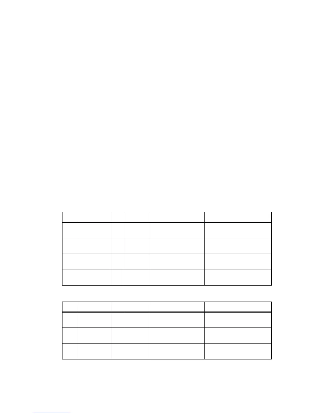
Table 7.3 Talk through repeater—mandatory settings
LINK Name Pins Position Function Comments
J400 Tx Key
Source
3 2-3 Talk Through Repeater
mode
Receiver gate keys transmitter
J502 Tx Audio
Source
3 2-3 Talk Through Repeater
mode
Transmitter audio taken from the
receiver
J503 Rx Audio
Destination
3 1-2 Talk Through Repeater
mode
Received audio to the transmitter
W401
W402
TOI 9V Enable
TOI 4.5V Enable
2
2
Not
fitted
Tone on Idle disable Tone on idle not used in repeater
configuration
Table 7.4 Talk through repeater—optional settings
LINK Name Pins Position Function Comments
J507 Line In
Destination
31-2
2-3
Tx Line In to Aux Mic
Tx Line In to Audio Tap In
Default position is 2-3
J206 Fan Control 1 3 1-2
2-3
Fan controlled by J207
Fan always on
Default position is 1-2
J207 Fan Control 2 3 1-2
2-3
Fan Tx key-controlled
Fan temperature-controlled
Default position is 2-3
 Loading...


