TB7100 Installation and Operation Manual Preparation for Operation 123
© Tait Electronics Limited December 2005
7.15 Relay Polarity
Relay operation can be configured to be energised when the receiver gate
is active or inactive.
7.15.1 Link Settings
Remove the cover as detailed in “Removing the Base Station and Opening
the Tray” on page 54 and set the jumper positions on the system interface
to match the table below. Replace the cover as detailed in “Final
Reassembly” on page 63. Refer to Figure 7.11 on page 115 for the link
location.
7.16 Channel Increment and Decrement by Function
Keys
Function button one and two can be configured to increment and
decrement the channels. This requires two links fitted to the rear of the user
interface board, this will hard wire the F1 and F2 buttons to the
increment/decrement function. It is recommended F1 & F2 have no other
programmed action.
This option will allow all 99 channels to be selected from the function
buttons.
For more information, refer to the technical note TN-1032-AN
“Implementing Channel Increment and Decrement on the TB7100”
available from http://support.taitworld.com.
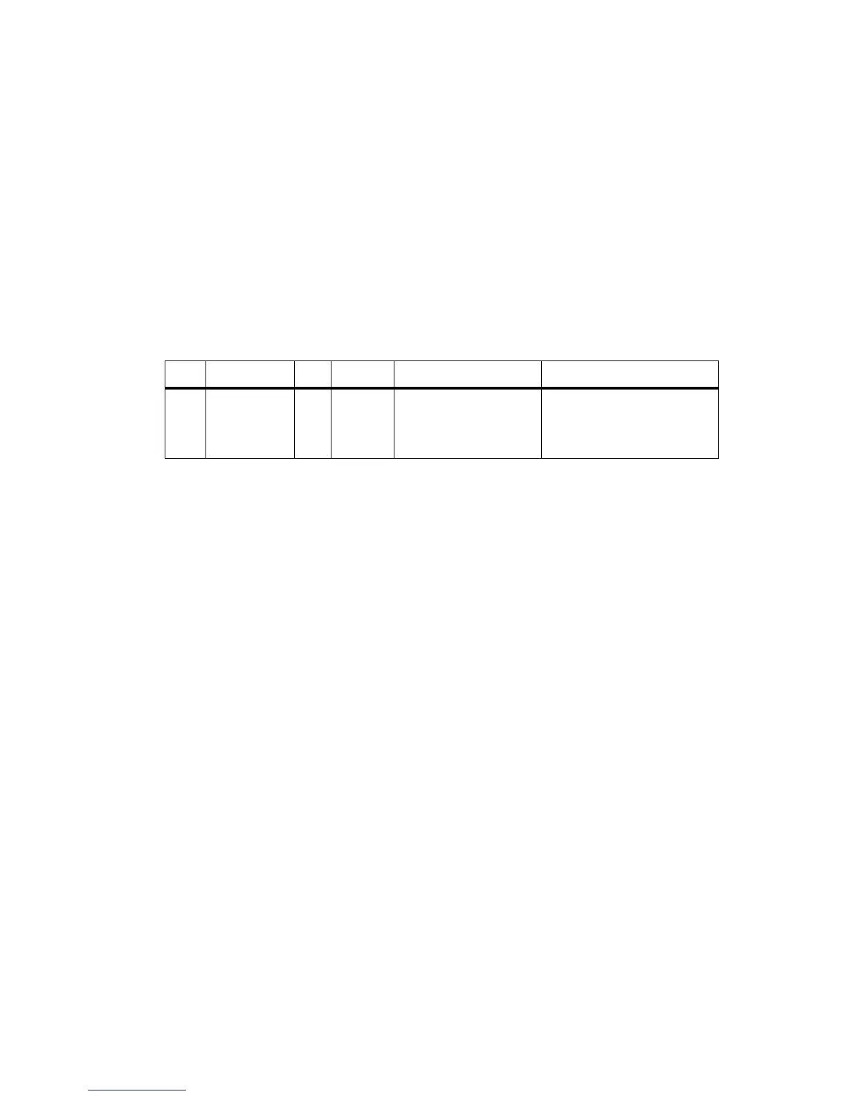
Table 7.13 Relay polarity—link settings
LINK Name Pins Position Function Comments
W401 Relay Polarity
Control
31-2
2-3
Energised for receiver active
gate
Energised for receiver
inactive gate
Default is 1-2

 Loading...


