TB7100 Installation and Operation Manual Replacing Modules 57
© Tait Electronics Limited December 2005
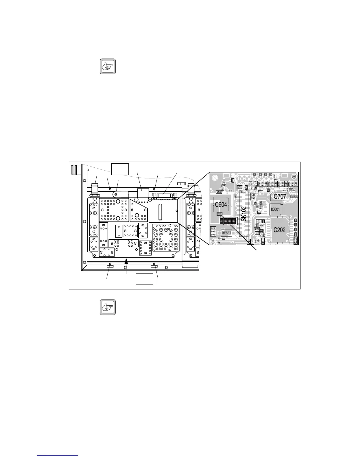
5.4 Replacing the Transmitter Module
Removal Note Release the latch underneath the DC power connector before
attempting to disconnect it.
1. Disconnect the cables to the RF
b, DC power c, system interface
d, and the user interface f connectors.
2. Use a Torx T10 screwdriver to remove the screw
h fastening the
temperature sensor to the heatsink.
3. Use a Torx T10 screwdriver to remove the four screws
g fastening
the heatsink to the tray chassis.
4. Lift the transmitter module clear of the tray chassis.
Fitting Note Although the boards of the transmitter and receiver modules look
alike, the board on the transmitter module can not replace a
receiver module. There is no heat transfer plate on the receiver
module. Check that the replacement module has links LK2, LK3
and LK4 not fitted as shown in Figure 5.4.
1. Position the transmitter module inside the tray chassis.
2. Use a Torx T10 torque-driver to fasten the four screws
g to 4.5lbf·in
(0.5N·m).
3. Use a Torx T10 torque-driver to fasten the temperature sensor with
the screw
h to 4.5lbf·in (0.5N·m).
4. Connect the cables to the RF
b, DC power c, system interface d,
and the user interface
f connectors.
Figure 5.4 Replacing the transmitter module
g
f
b
c
d
g
e
Check that links LK2, LK3 and
LK4 are not fitted.
g
g
g
h
Torx T10
4.5lb·in
Torx T10
4.5lb·in
Cables not shown.

 Loading...


