TB7100 Installation and Operation Manual Replacing Modules 63
© Tait Electronics Limited December 2005
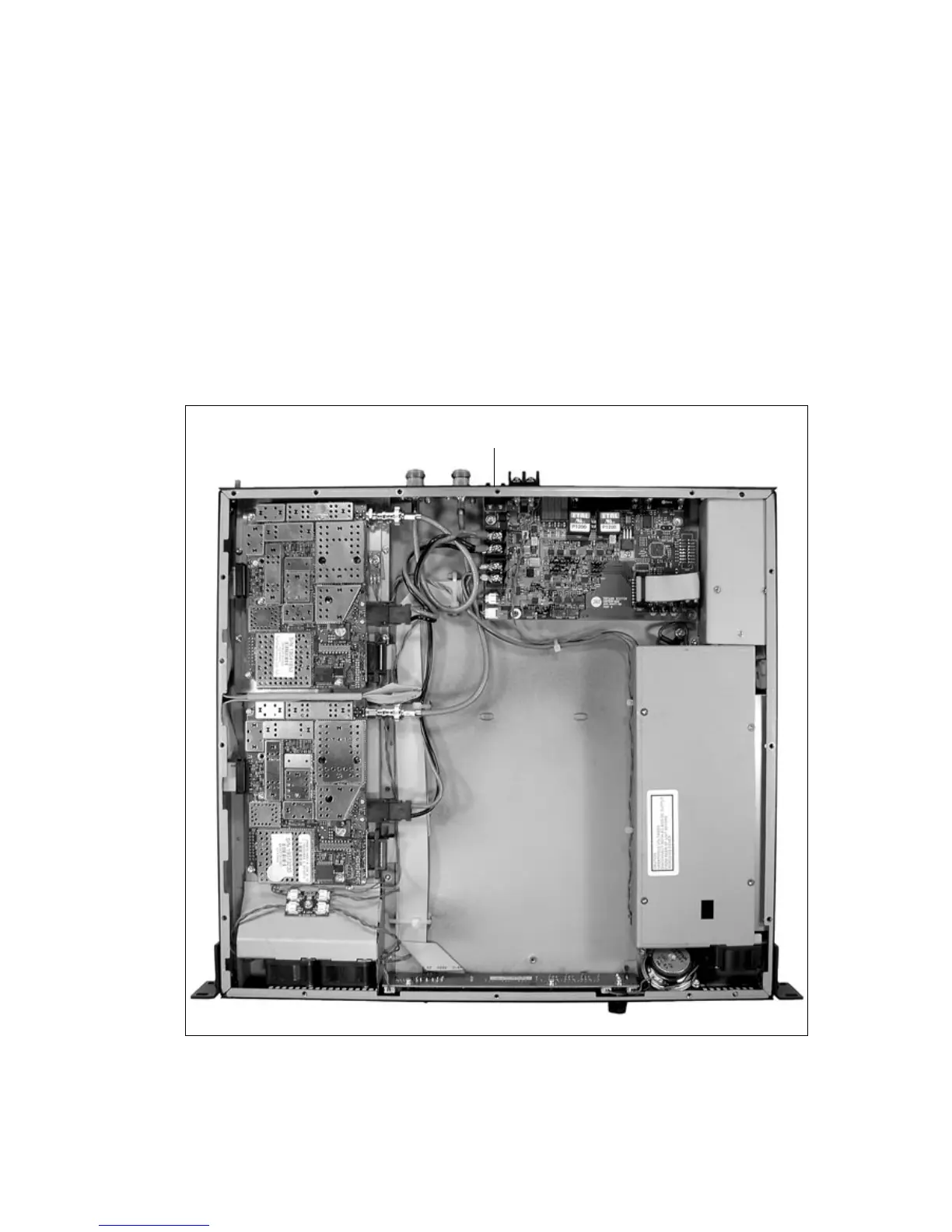
5.11 Final Reassembly
Figure 5.8 shows the assembled configuration with internal AC power
supply unit. Figure 5.9 shows the assembled configuration without internal
AC power supply unit.
1. Ensure all internal cables are connected correctly as shown below.
2. Place the tray cover onto the chassis.
3. Use a Torx T10 torque-driver to fasten the tray cover with the 15
countersunk screws to 4.5lb·in (0.5N·m).
4. Fit the fuse b at the rear of the base station.
Figure 5.8 Final reassembly (configuration with internal AC power supply unit)
Fuse

 Loading...


