94 Preparation for Operation TB7100 Installation and Operation Manual
© Tait Electronics Limited December 2005
Calibration Test Unit
(CTU)
The CTU is used to configure and test the base station. The same CTU is
used for TB8000 and TB9000 base station equipment, so only some of the
features on the CTU apply to the TB7100 base station. The CTU adaptor
is plugged into the system connector of the CTU. The CTU cable is
plugged into the system connector of the base station.
For more information on the CTU refer to the TBA0STU/TBA0STP
Calibration and Test Unit Operation Manual (MBA-00013-xx).
7.5.2 Test Equipment Setup
1. Connect the PC to the programming port on the front panel of the
base station. See “Connecting to the PC” on page 105.
2. Connect the receiver N-type connector to the RF test set (signal
generator) output port.
3. Connect the transmitter N-type connector to the RF test set (power
and modulation meter) input port, check the test set is rated for the
transmit power of the base station.
4. Connect the 13.8V power supply to the DC input on the base
station, ensuring correct polarity.
7.5.3 Link Settings
Remove the cover as detailed in “Removing the Base Station and Opening
the Tray” on page 54 and set the following links on the SI board.
Links of the mandatory settings must be in the position indicated. Links of
the optional settings must be in one of the positions listed. The defaults are
generally recommended.
Replace the cover as detailed in “Final Reassembly” on page 63.
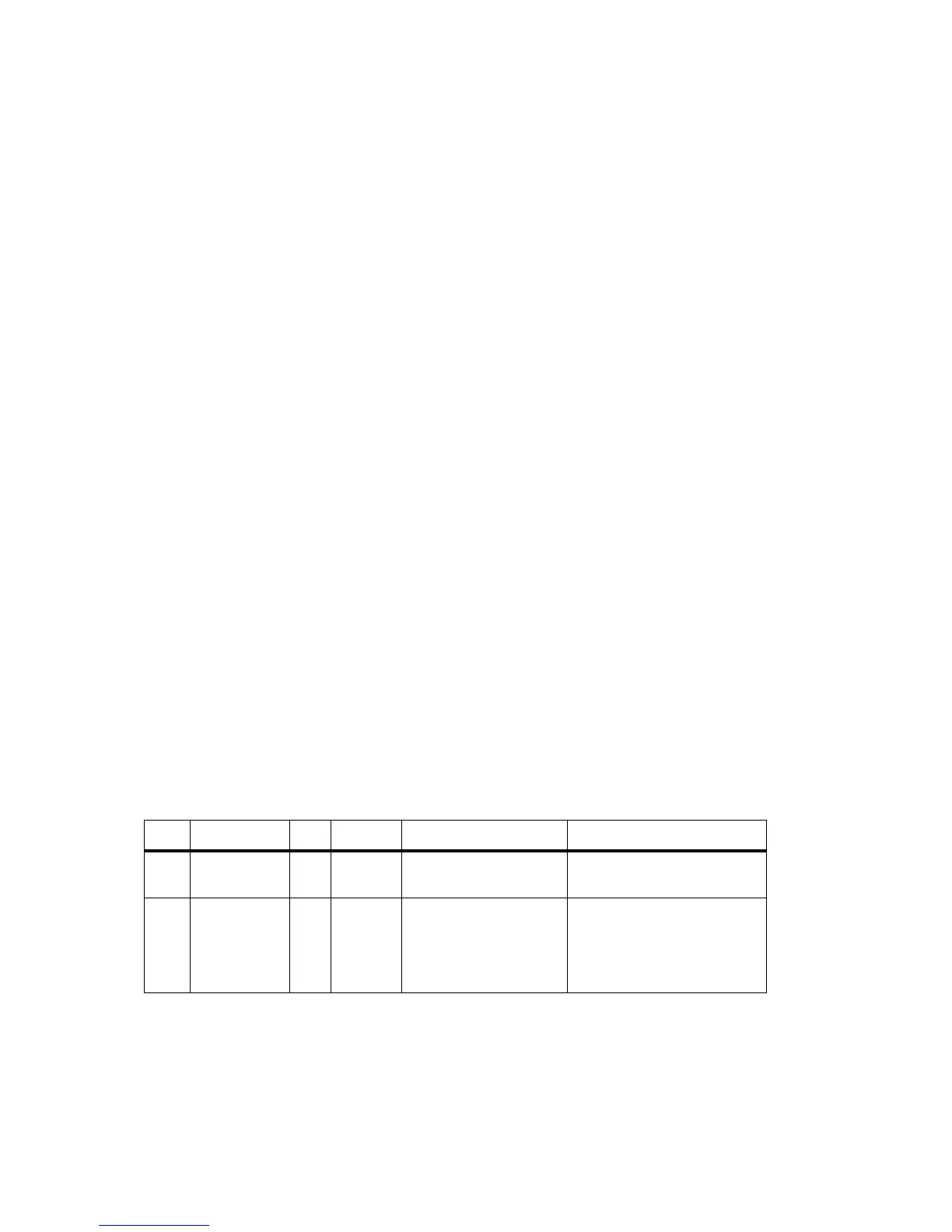
Table 7.5 RF modem—mandatory settings
LINK Name Pins Position Function Comments
J221 RS232 Loop
Back
3 1-2 RS-232 out data connector
J400 Tx Key
Source
3 1-2 External Tx key source Use this setting because the
transmitter will automatically key
up when there is data to send so
should not be keyed by the
receiver gate.

 Loading...


