4-109
4
PILOT VALVE (TRAVEL)
DISASSEMBLY AND ASSEMBLY
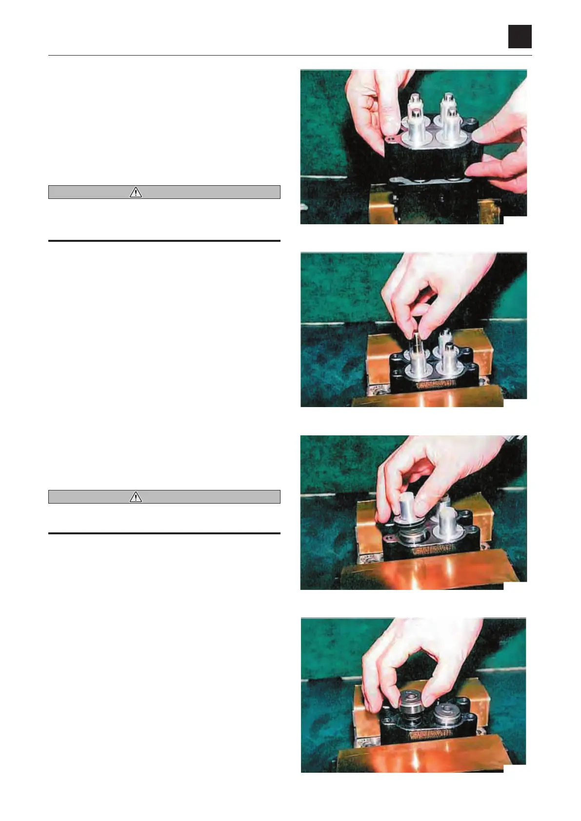
8. Remove the upper casing assembly and fix it in a vise.
• Note down the relative position of the upper casing
assembly so that it can be installed in the position it
was in before disassembly.
9. Pull out the push rods from the plugs.
• Note down the relative positions of push rod so that
it can be installed in the position it was in before
disassembly.
WARNING
• When removing the push rod, there is a risk that the
plug may pop out.
• Take care not to scratch the push rod surface.
10. Remove the plugs together with the grease cup, pack-
ing and O-ring.
• Note down the position of the plugs relative to the
casing.
WARNING
When removing the plugs, there is a risk that the piston
may pop out due to the damping spring force.
11. Remove the pistons.
• Note down the position of the pistons relative to the
casing hole.