2-58
Fig. 2.152
Fig. 2.154
Fig. 2.153
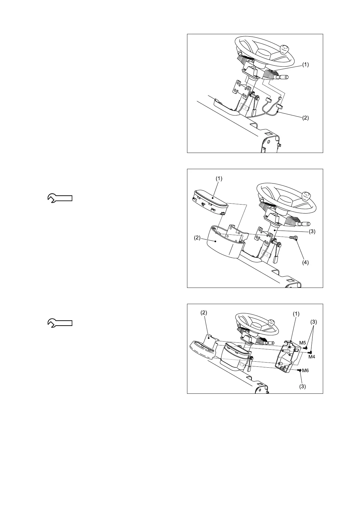
④ C o n n e c t t he w i r e h a r ne s s ( 2 ) t o t h e
combination switch (1).
⑤ Install the combination meter (1) and cover C
(2) on the steering wheel column (3) using the
bolts (4).
3.2 - 4.8 N-m {0.3 - 0.5 kgf-m}
[2.4 - 3.5 lbf-ft]
⑥ Install the covers A (1) and B (2) using the
bolts (3).
M4: 1.2 N-m {0.12 kgf-m} [0.89 lbf-ft]
M5: 2.4 N-m {0.24 kgf-m} [1.77 lbf-ft]
M6: 5.0 N-m {0.4 kgf-m} [3.69 lbf-ft]