2-2
Fig. 2.7
Fig. 2.5
Fig. 2.6
Fig. 2.8
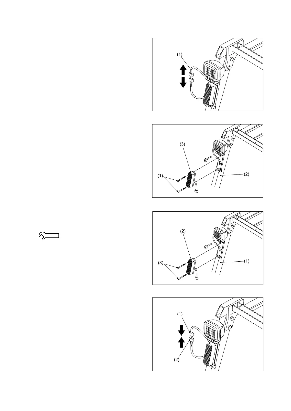
2.1.2 FRONT COMBINATION LAMP
■ REMOVAL
① Disconnect the connector of the front
combination lamp from the connector of the
wire harness (1) on the overhead guard.
② Remove the two screws (1) and then remove
the front combination lamp (3) from the
overhead guard (2).
■ REINSTALLATION
① Install the front combination lamp (2) on the
overhead guard (1) using the two screws (3).
1.9 - 2.8 N-m {0.2 - 0.3 kgf-m}
[1.4 - 2.1 lbf-ft]
② Connect the connector (2) of the front
combination lamp to the connector of the wire
harness (1) on the overhead guard.