2-55
Fig. 2.143
Fig. 2.145
Fig. 2.144
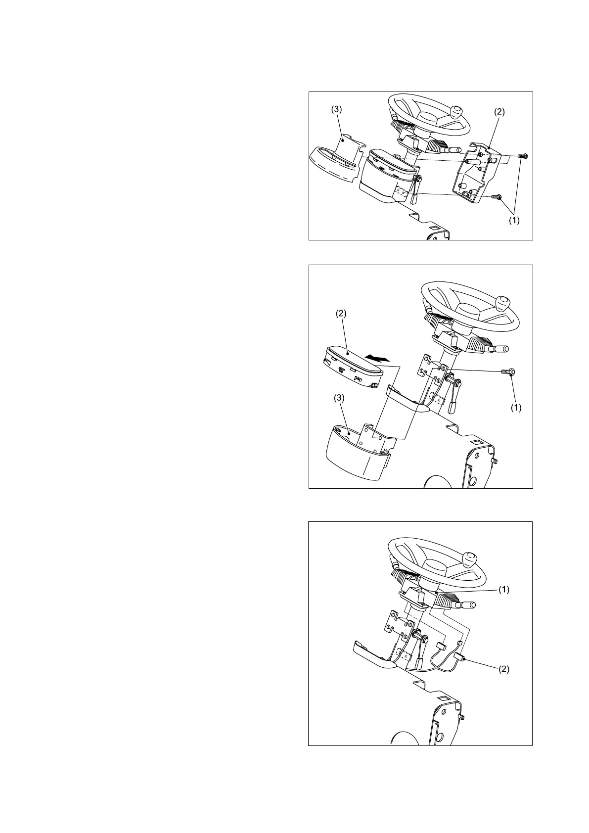
2.13 STEERING WHEEL
■ REMOVAL
① Remove the bolts (1), and then remove the
covers A (2) and B (3).
② R e m o v e th e b o l t s ( 1 ) a n d m o v e t h e
combination meter assembly (2) toward the
front guard side.
(At this point, the wire harness must remain
connected.)
Remove the cover C (3).
③ Remove the wire harness (2) from the
combination switch (1).