3-114
Fig. 3.370
Fig. 3.373
Fig. 3.372
Fig. 3.371
3.9 MAIN PUMP
■DISASSEMBLY
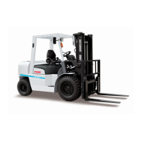
① Hold the front cover (2) in a vise with the
input shaft (1) side downward.
Note: 1.
The bolts will be loosened during
disassembly. Make sure to hold the front
cover in a vise securely as shown in Figure
3.370, to prevent the pump from the vise
when a force is applied on the pump.
2. Mark the rear cover (3), adapter (4), and
front cover (2), and the drive gear side
of the pump body half 2 (5) and pump
body half 1 (6) with oil paint.
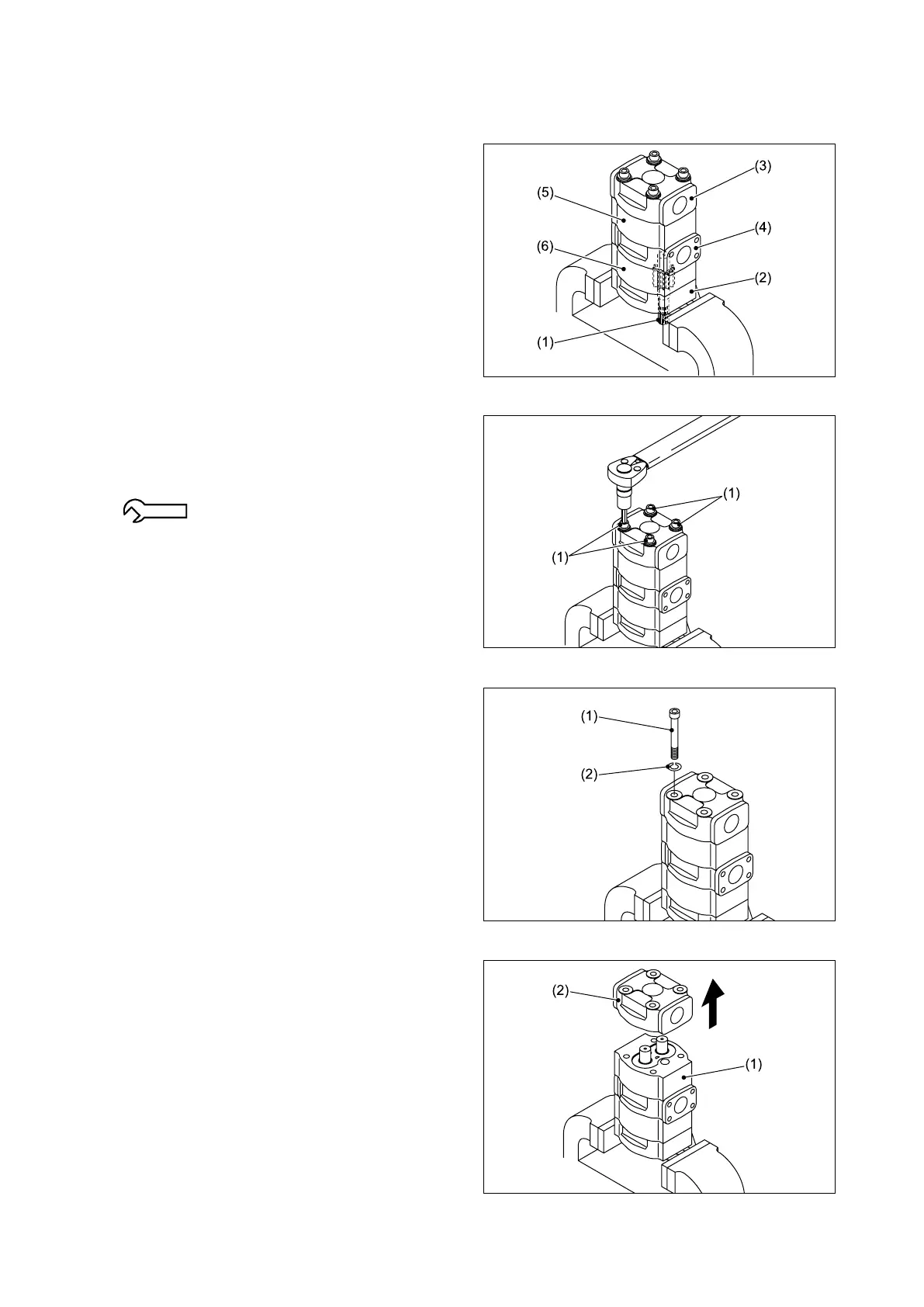
② Turn the four fitting bolts (1) with a torque
wrench in the tightening direction, to check
whether they are properly tightened to the
speciedtorque.
88.3 - 98.1 N-m {9 - 10 kgf-m}
[65.1 - 72.3 lbs-ft].
③ Remove the four fitting bolts (1) and four
spring washers (2).
④ Remove the rear cover (2) by tapping the side
face of the pump body half 2 (1) with a plastic
mallet.
If the gaskets remain inside the pump body
half 2 (1), move them toward the rear cover (2)
side.