2-3
Fig. 2.11
Fig. 2.9
Fig. 2.10
Fig. 2.12
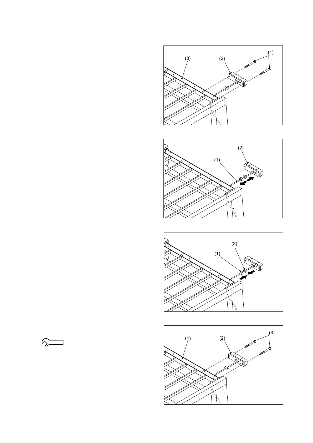
2.1.3 REAR COMBINATION LAMP
■ REMOVAL
① Remove the screws (1) and then remove the
rear combination lamp (2) from the overhead
guard (3).
② Di sco nn ect t he c onnec to r of th e rea r
combination lamp (2) from the connector of
the wire harness (1) on the overhead guard.
■ REINSTALLATION
① Connect the connector (2) of the rear
combination lamp to the connector of the wire
harness (1) on the overhead guard.
② Install the rear combination lamp (2) on the
overhead guard (1) using the screws (3).
1.9 - 2.8 N-m {0.2 - 0.3 kgf-m}
[1.4 - 2.1 lbf-ft]