3-67
Fig. 3.214
Fig. 3.217
Fig. 3.216
Fig. 3.215
3.3 DRIVE AXLE
■ DISASSEMBLY
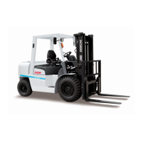
① Straighten the lock washer (1) tabs and
remove the lock nut (2) and lock washer (1).
② Remove the adjustment nut (1).
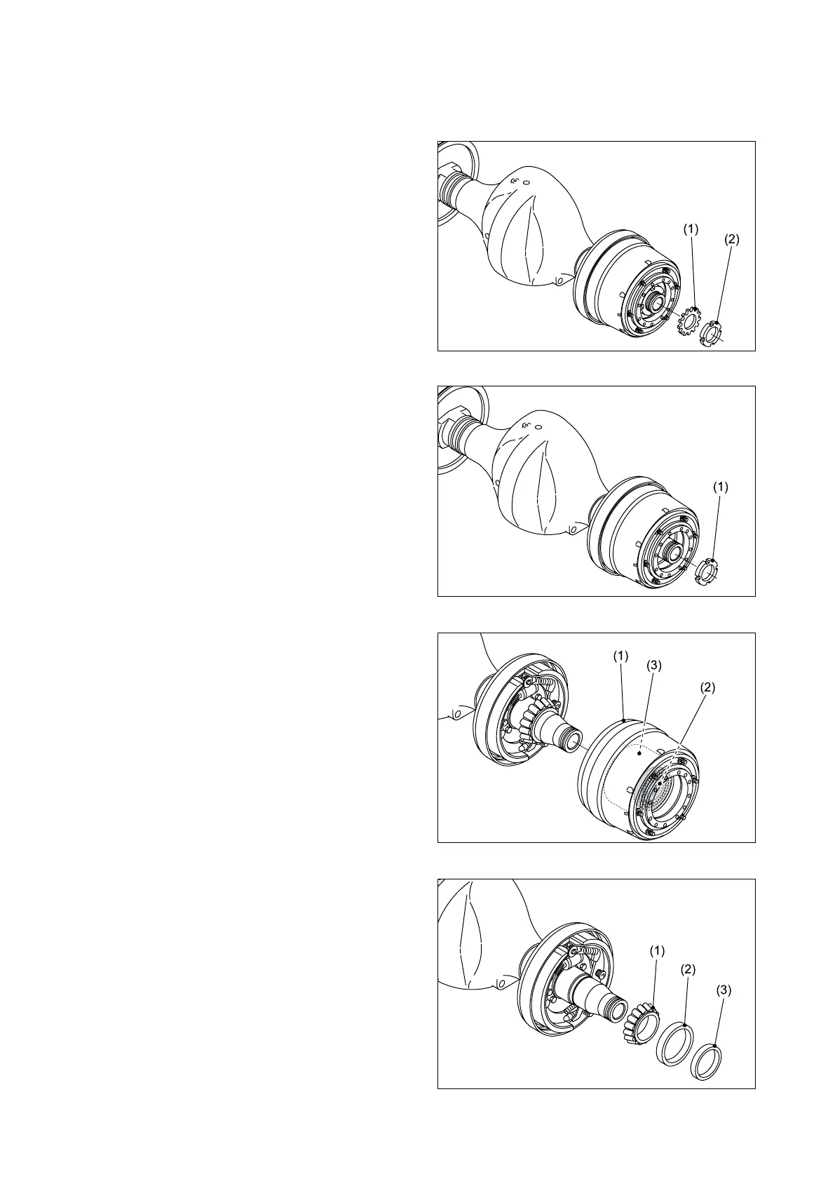
③ Using a puller, remove the hub (3) together
with the drum (1) and outer tapered roller
bearing (2).
④ Remove the cone (1), oil seal (2) and retainer
(3) from the inner tapered roller bearing.
Note: Put an identifying mark (or number) on
each set of tapered roller bearings, so that
you can distinguish one set from another.