2-60
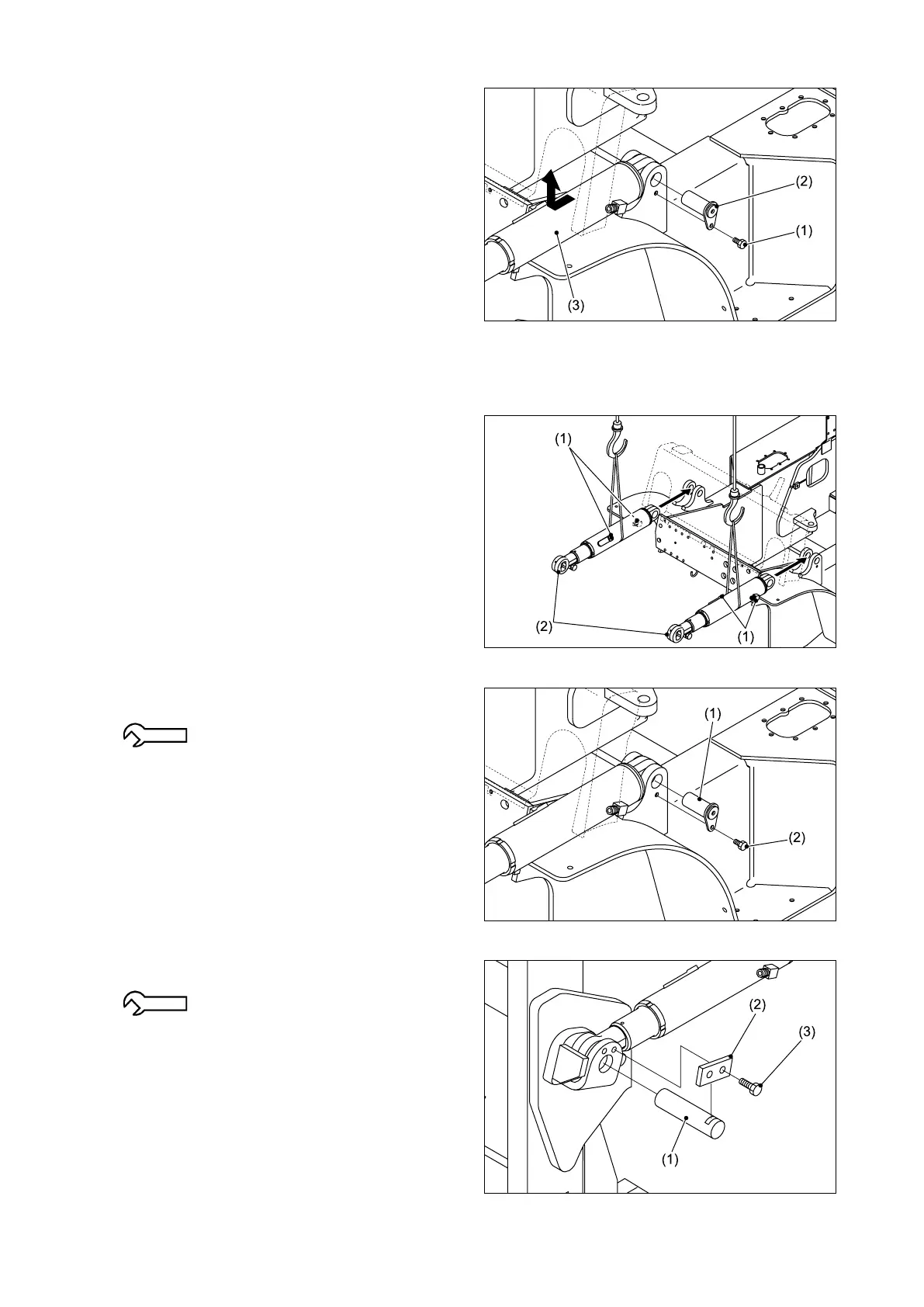
Fig. 2.158
Fig. 2.161
Fig. 2.160
Fig. 2.159
④ Rem ove the bolts (1 ) and rem ove the
connecting pins (2) from the frame. Then
remove the tilt cylinders (3).
■ REINSTALLATION
① Place each tilt cylinder (2) in the mounting
position on the frame. Pay attention to the
positions of the right and left hydraulic ports
(1).
② Install the connecting pin (1) at the frame side
and then secure it using the bolts (2).
17.1 - 25.4 N-m {1.74 - 2.59 kgf-m}
[12.6 - 18.7 lbf-ft]
③Install the connecting pin (1) at the mast side
and secure it using the plate (2) and bolts (3).
17.1 - 25.4 N-m {1.74 - 2.59 kgf-m}
[12.6 - 18.7 lbf-ft]