• Calculation specification for the angle correction:
Raw sensor data + Sensor correction + Installation correction = Vehicle Inclination
(see also pre-testing models DOK-476 inclination sensor)
• Procedure for inputting the angle corrections:
1. Entry of the correction values from the pre-acceptance test certificate
2. Alignment of the vehicle to 0° in both directions
3. The installation corrections are entered in the parameter list by means of ‘ZEROING’
the system!
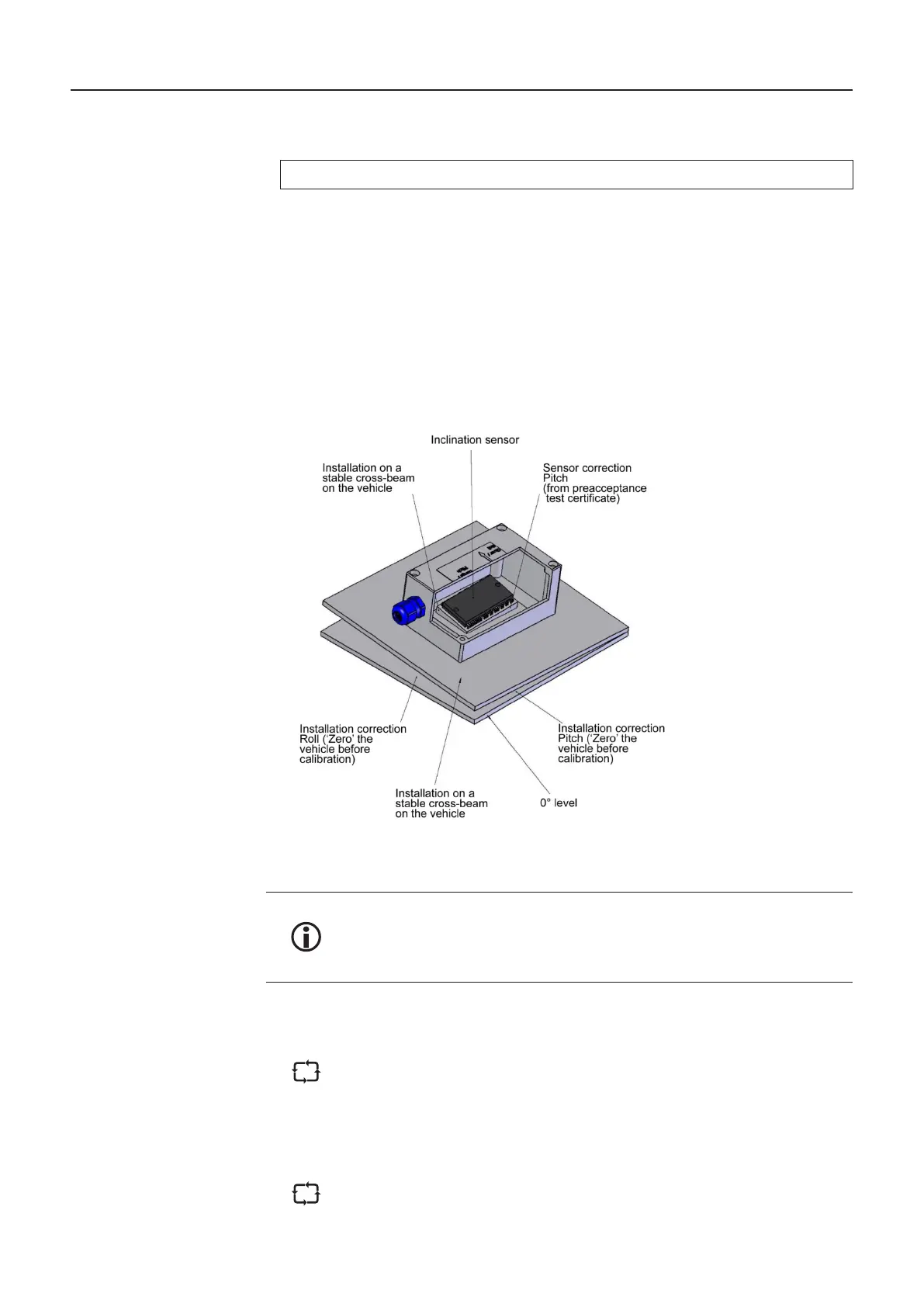
Figure 17: Inclination sensor (drawing: 51.251917)
By dividing the correction value into sensor correction and installation
correction, the inclination sensor can be exchanged without having to bring
the vehicle into the normal position again. It is only necessary to transfer
parameter table.
5.7.4. X / Y Correction
The inclination correction values are generated by means of a PC and a
3D-CAD program for the target position of the level sensor. If the position of
the level sensor does not correspond to the target position due to manufacturing
are particularly large if the deviations from the target position occur in the
longitudinal or transverse direction of the vehicle.
The deviation can be compensated by means of computational shift of the
level sensor in the longitudinal and transverse direction of the vehicle.
MultiLevel Instruction Manual Description of the Level Gauging System