STEP 600 XTPRO: Service & Maintenance Manual - rev. 1.1
Page 3.5
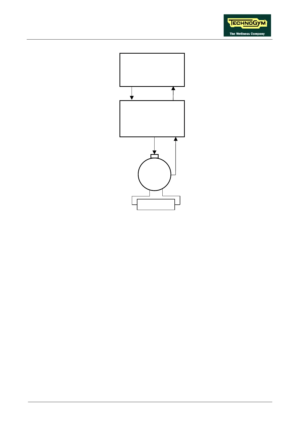
The control utilizes the following signals:
• Excitation signal (PWM)
This is the signal generated by the CPU board (pin 6-3 of connector CN1) to control the resistor.
It is a PWM signal, that is to say a fixed-frequency square wave signal with variable duty cycle.
The logic of this control has the duty cycle increasing with increasing resistance. Measuring its
DC component with a multimeter will show that its value increases with increasing resistance,
from a minimum of a few hundred mV up to approximately 5 Vdc.
This signal enters the alternator interface board (pin 6-3 of connector CN1) and is sent to the
alternator (pin 4-5 of connector CN2 on the alternator interface board) to supply its rotor via the
brushes.
• RPM Signal
This is the speed signal output by the alternator. It enters the alternator interface board (pin 1-5
of connector CN2) and is a square wave which varies from –1 Vdc to a maximum value
dependent on the training speed, as illustrated in the figure below:
CPU board
Alternator interface
board
RPM
PWM
6-3
5-3 CN1
6-3
5-3 CN1
4-5 1-5 CN2
Alternator
RPM
PWM
Resistor