STEP 600 XTPRO: Service & Maintenance Manual - rev. 1.1
Page 7.3
7.2. DISASSEMBLING THE EPROM
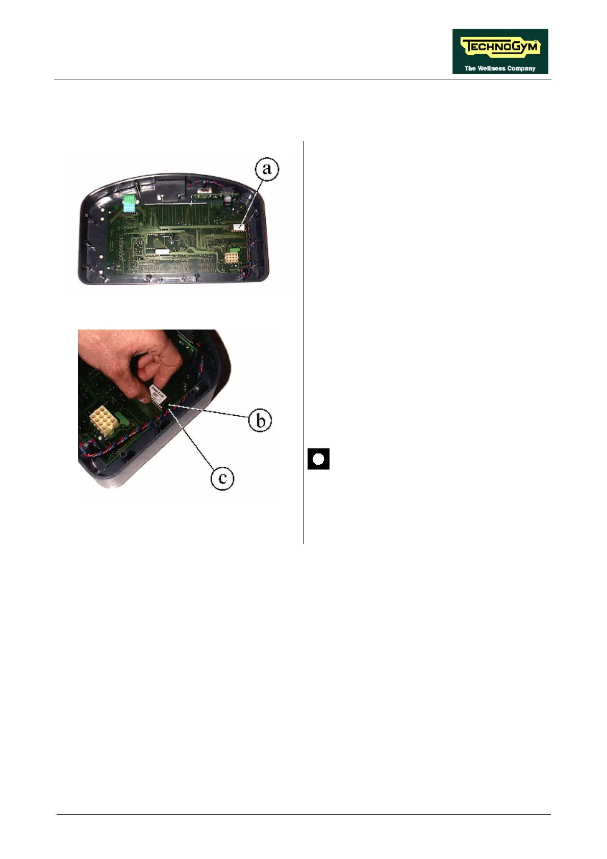
Figure 7.2-1
Carry out the procedure described in paragraph
7.1. “Disassembling the display”.
With the display on a work bench:
1. Remove EPROM a from its socket using an
integrated-circuit extractor tool.
Figure 7.2-2
To reassemble the EPROM:
1. Make sure that reference index b on the
EPROM coincides with reference notch c on
the socket.
2. Be careful to center the EPROM pins above
their corresponding holes in the socket.
3. Push the pins into the socket.
The EPROM can be irreversibly
damaged if the reference index on the
EPROM is not correctly aligned with the
notch on the socket, or if its pins are
bent.