STEP 600 XTPRO: Service & Maintenance Manual - rev. 1.1
Page 7.8
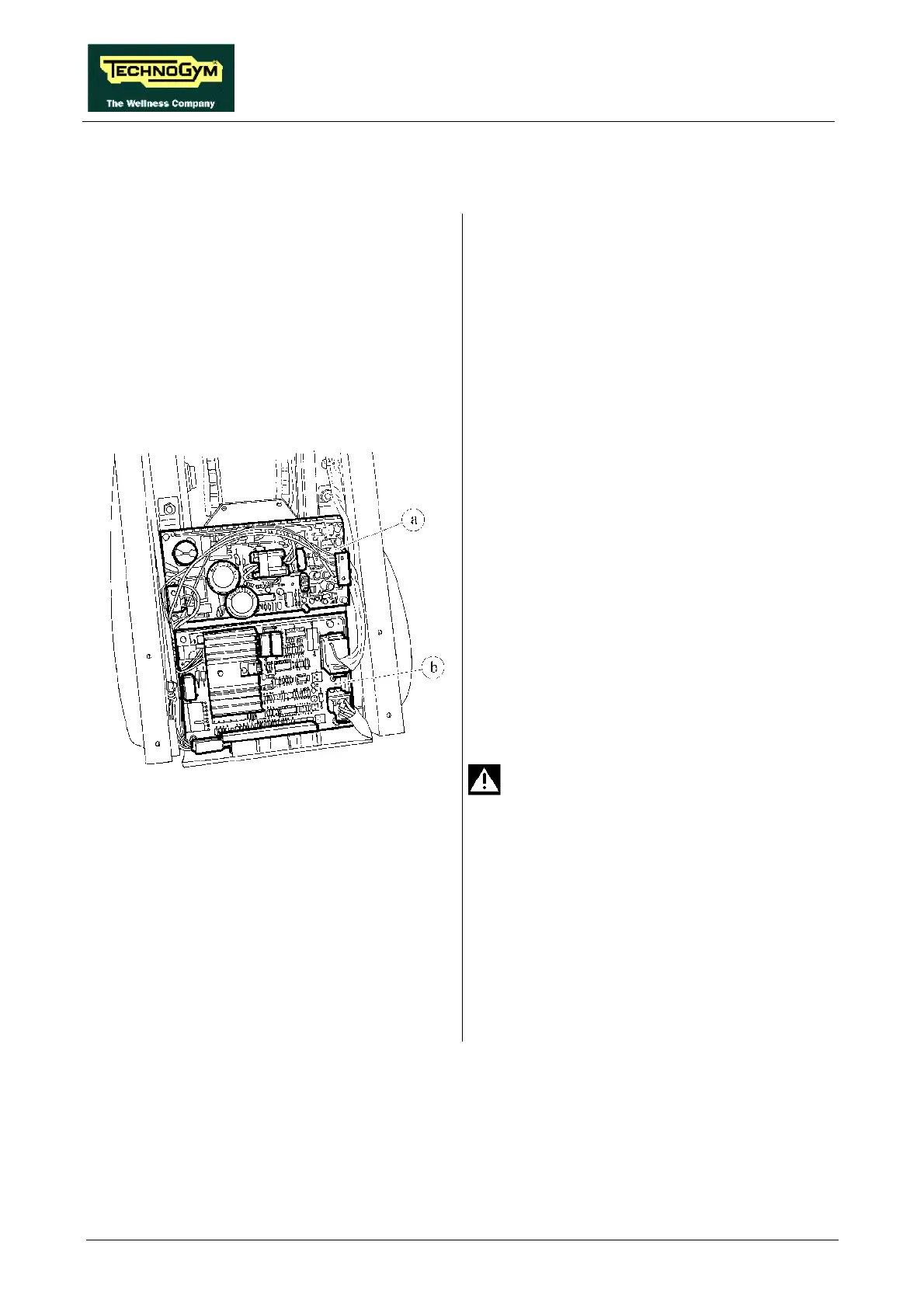
7.7. DISASSEMBLING THE ELECTRONIC CIRCUIT BOARDS
Figure 7.7-1
Carry out the procedure described in paragraph
7.6. “Disassembling the upright guard”.
To disassemble the POWER SUPPLY a:
1. Disconnect the 2 connectors CN1 and CN2.
2. Disconnect the grounding fast on.
3. Remove the screws fixing it to the support
plate using a 7-mm socket wrench.
4. Remove the circuit board.
To disassemble the ALTERNATOR
INTERFACE BOARD b:
1. Disconnect the 3 connectors CN1, CN2 and
CN3.
2. Remove the 4 screws fixing it to the support
plate using a 7-mm socket wrench.
3. Remove the circuit board.
To disassemble the POWER RESISTOR, which
is situated at the rear of the circuit board support
plate:
Check that the resistor is not hot.
1. Unscrew the 2 locknuts of cable SX-5/L
using a 7-mm wrench.
2. Unscrew the 2 locknuts of the resistor using a
10-mm wrench.
3. Remove the resistor.
To reassemble the ELECTRONIC CIRCUIT
BOARDS, carry out the above steps in reverse
order.