STEP 600 XTPRO: Service & Maintenance Manual - rev. 1.1
Page 6.12
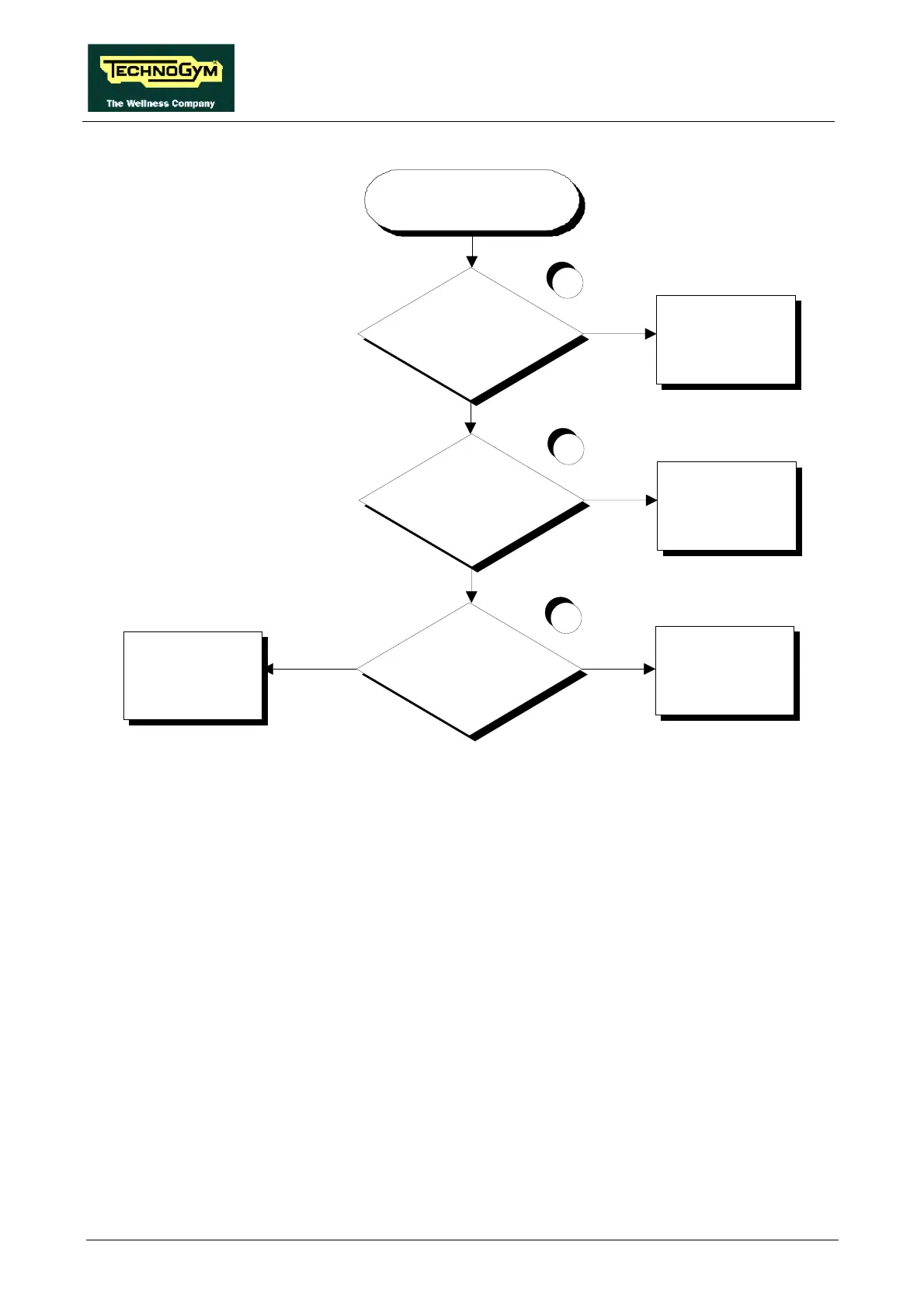
Are the sensors correctly
connected to the HS interface
board?
Does the correct supply voltage
reach connector CN7 of the
CPU board?
Reinstate the connection
Replace or rewire the cable
connecting the CPU board
to the HS interface board
Replace the CPU board of
the control panel
1
3
YES
NO
YES
NO
Does the correct supply voltage
reach connector HD4 of the HS
interface board?
Replace the HS interface
board
2
YES
NO
THERE IS NO HEART
RATE SIGNAL
Follow the procedure step by step to correctly diagnose the problem. Take particular care with the
checks highlighted by circled numbers, which are described in detail below:
(1) Check the connections, referring to paragraph 2.5. “Wiring diagram with non-coded receiver”.
(2) Place the tester probes between pins 2 and 1 of connector HD4 on the HS interface board: the
measured voltage should be +5 Vdc.
(3) Place the tester probes between pins 4 and 2 of connector CN7 on the CPU board: the
measured voltage should be +5 Vdc.