ENGLISH
User’s manual 50 UPS EVO DSP PLUS Modular
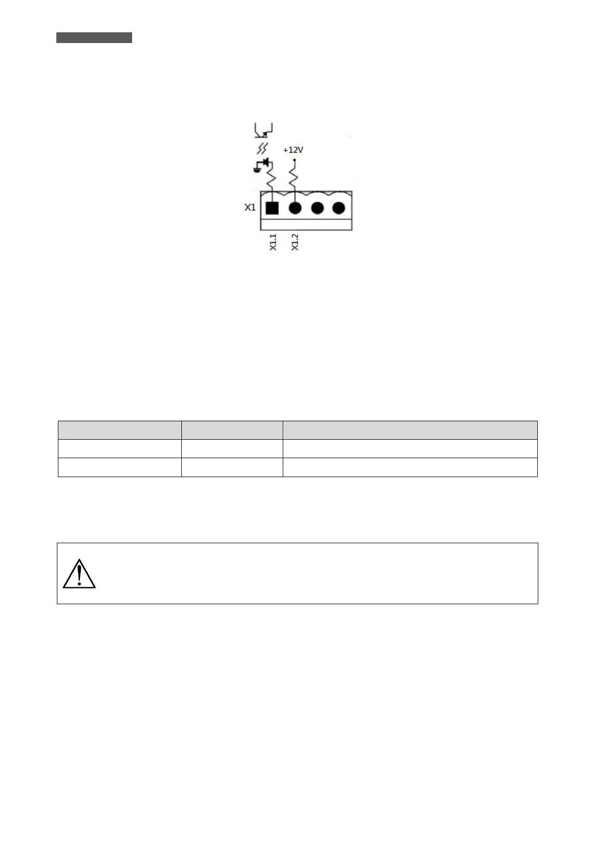
7.1.1.1 X1-Remote EPO Input Port
X1 is the Remote EPO Input Port.
The port is shown in Figure 7.3 and described in Table 7-1.
Figure 7.3 – X1-Remote EPO Input Port
The Emergency Power off (EPO) Function in UPS can be operated by an assigned remote contact.
To activate the EPO Function, simply connect an external contact to Pin X1.1 and Pin X1.2 of the EPO Input
Port.
The logic of activation of the EPO function can also be set via the LCD panel: the logic can be N.C. (Normally
Closed contact) or N.O. (Normally Open contact).
The EPO activation causes immediate UPS shutdown.
Table 7-1: Description of EPO Input Port
If EPO Logic setting is Normally Closed (N.C.), EPO is triggered when Pin X1.1 and Pin X1.2 are opened. Otherwise,
EPO Logic setting is Normal Opened (N.O.). EPO is triggered when Pin X1.1 and Pin X1.2 are closed.
The EPO terminals are isolated and do not need an external feeding Voltage.
EPO function activates shutdown of the Rectifiers, Inverters and Static Transfer Switch.
But it does not internally disconnect the input power supply.
The default setting of the EPO function logic is Normally Opened (N.O.).