Checks and Adjustments
5–4
1720/1721
14. Dual Input Coupler
Matched BNC cable-T for making phase comparisons between two inputs.
Matched length of the two arms within ±0.1 inch.
For example: Tektronix Part No. 067–0525–02.
15. Precision 50Ω Coaxial Cable
Tektronix Part No. 012–0482–00 (used with the TEKTRONIX SG503).
16. 50Ω to 75Ω Minimum Loss Attenuator
Tektronix Part No. 011–0057–00.
17. Female to Female BNC adapter
Tektronix Part No. 103–0028–00
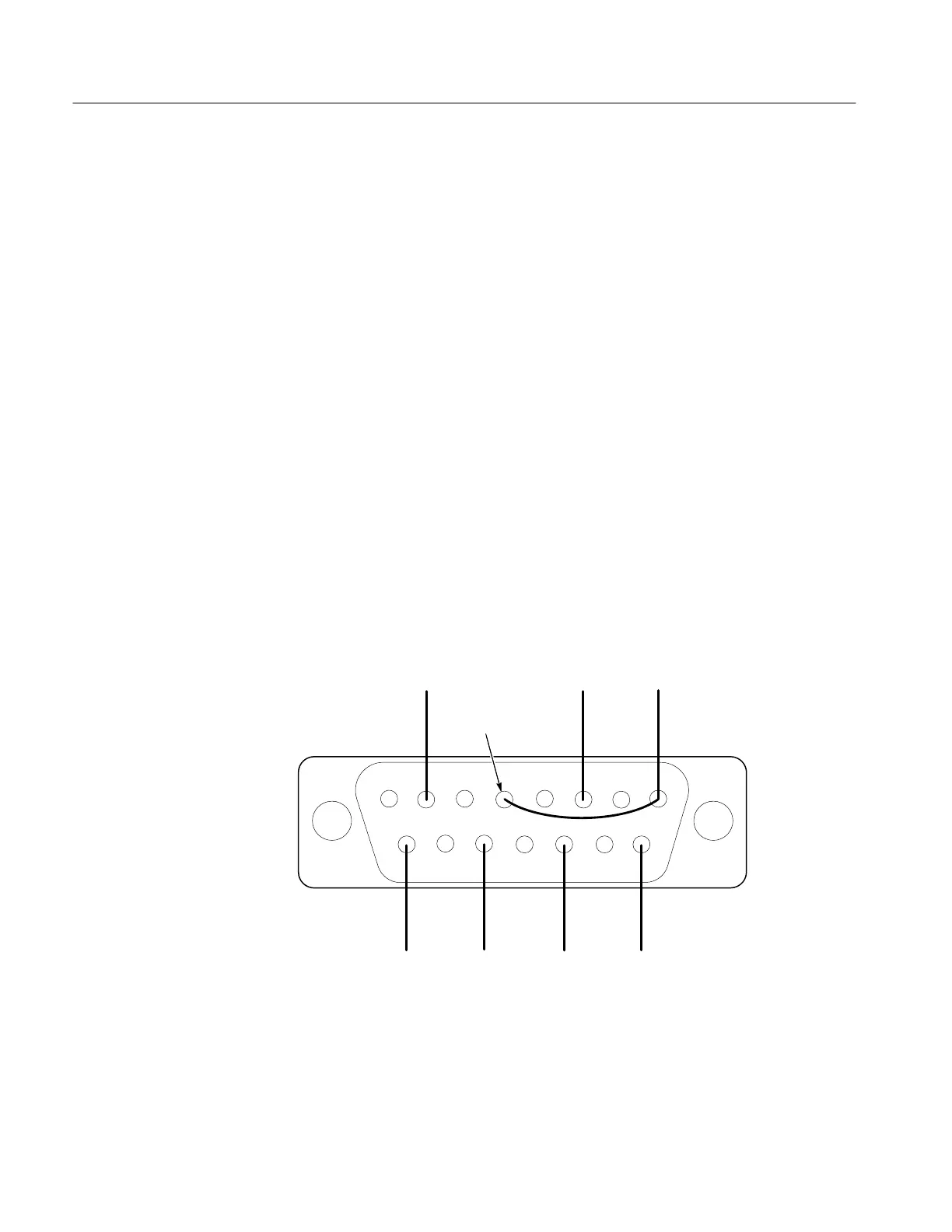
18. XY Input Connector Parade Display Test Connector
Fifteen-pin, subminiature D-type connector (for example: Tektronix Part
No. 131–0459–00), modified to input signals for XY checks and adjust-
ments. See Figure 5-1.
12345678
9101112131415
Soldered-in wires need to be long
enough to permit shorting together.
+Y
INPUT
+Y HIGH
GAIN
INPUT
–X
INPUT
+X
INPUT
–Y INPUT
+X HIGH
GAIN
INPUT
–Y
INPUT
–X
INPUT
Figure 5-1: Rear view of XY INPUT plug connections. Note that High Gain inputs are
shown even though they are not normally used in these procedures.